Lift Arm Control Valve
Removal
1. Perform the footwell removal procedure on page 7-
4 of this manual.
2. Drain the hydraulic system as described on page
4-15 of this manual.
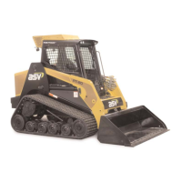
3. Label all lines and hoses as necessary to aid in
reassembly. (fig. 10-12)
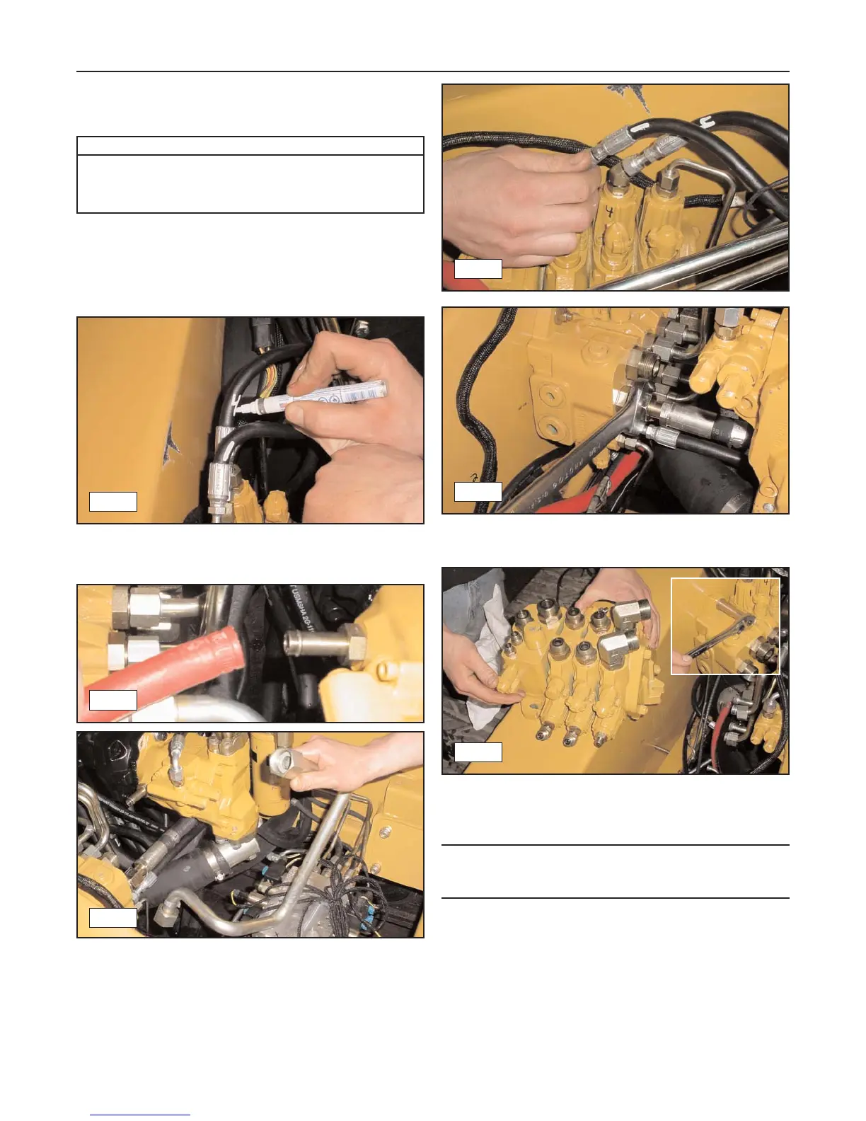
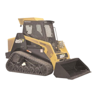
4. Disconnect the hose from the barb type fitting on
the auxiliary pump and the large hard line that
sweeps across the front of the pumps and con-
nects to the filter head to provide additional clear-
ance for line removal. (fig. 10-13, 10-14)
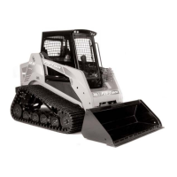
5. Disconnect all lines and hoses from the valve to
allow for removal. (figure 10-15, 10-16)
6. Remove the carriage bolts (3) securing the loader
valve to the chassis, Then remove the valve.
Note: The bolts have a square shank that mates with
a square hole in the chassis to keep them from rotat-
ing upon removal.
Installation
1. To install the lift arm control valve, reverse the
removal procedure.
10-4
Rubber Track Loader
10. Lift-Arm/Drive Controls
Required Tools
Socket Wrench
Combination/Open End Wrench
Screwdriver (hose clamps)
10-12
10-13
10-14
10-15
10-16
10-17