11-5
Rubber Track Loader
11. Hydraulic Pumps/Motors
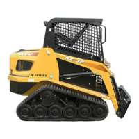
3. Support the pump with a hoist or floor jack to pre-
vent it from falling as the mounting bolts are
removed. (fig. 11-16)
4. Remove the upper and lower mounting bolts from
the drive pump. (fig. 11-17)
5. Remove the drive pump from the machine.
Installation
1. To install the drive pump, reverse the removal pro-
cedure.
Note: Torque the tandem pump mounting bolts to 85 lb. ft.
and use blue Loc-tite or equivalent to secure the bolts in
position.
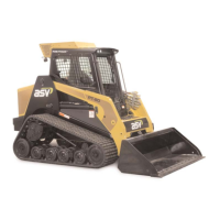
11-13
To
Oil Cooler
(return)
To
Drive Motor
(LT)
To
Drive Motor
(RT)
From
Charge
Filter
BTM BTM
BTM BTM
TOP
BTM
Top & Bottom Drive Pump Hoses
• View is from the top.
• The pump is to be perceived as transparent.
• Ports are labeled top or bottom as they are on the pump.
REAR
FRONT
RIGHT
LEFT
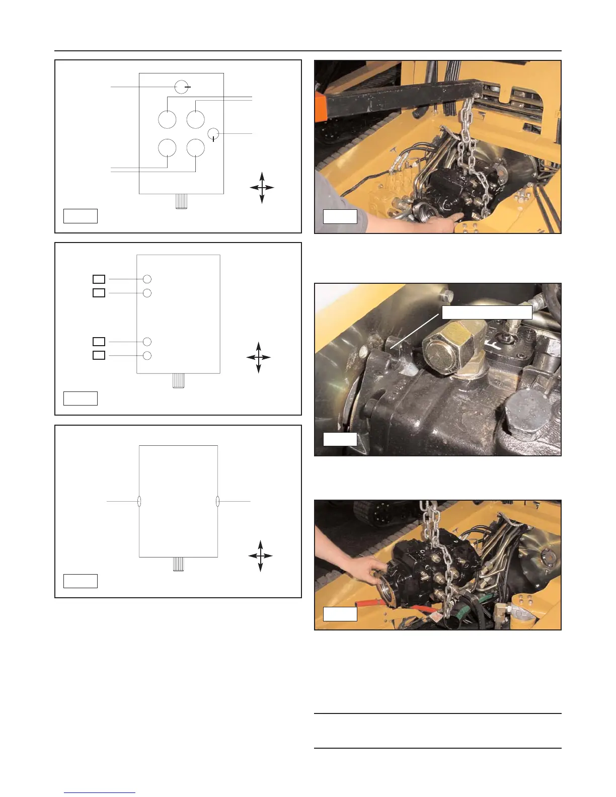
11-14
TOP
BTM
TOP
BTM
REAR
FRONT
RIGHT
LEFT
Top & Bottom Control Hoses
E
C
F
D
• View is from the top.
• The pump is to be perceived as transparent.
• Ports are labeled top or bottom as they are on the pump.
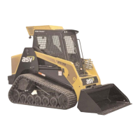
11-15
REAR
FRONT
RIGHT
LEFT
Side Drive Pump Hoses
From
Pilot Gen
Block
To
Pilot Gen
Block
• View is from the top.
11-16
11-17
Remove Bolts (2)
11-18