7 MAINTENANCE
107
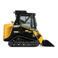
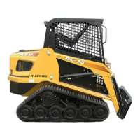
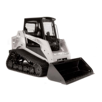
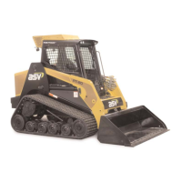
7.12 General Undercarriage Information
The undercarriage assemblies typically operate in harsh working conditions. They
work in mud, gravel, debris and various other abrasive materials during operation.
A daily inspection of the undercarriage assemblies (and cleaning if necessary) is
recommended.
Materials that are particularly sticky or abrasive like clay, mud, or gravel should
be cleaned from the undercarriages often to minimize component wear. A pres-
sure washer works well for cleaning materials from the undercarriages. At times
when a pressure washer is not available, use a bar, shovel or similar device to
carefully remove foreign materials.
When cleaning, pay particular attention to the drive motors/sprockets and the
front and rear wheels where debris is likely to accumulate. If working in scrap or
debris, inspect the undercarriages more often and remove foreign objects that
may wrap around or lodge themselves between components causing premature
wear and damage.
Operation on sand, turf, or other finished surfaces may require less frequent
cleaning, but daily inspection is still advised.
7.13 Track Tension Check
Proper track tension is important for achieving both optimum performance and
maximum track and undercarriage life. Always operate with track tension
within the specified range. Operating with tracks that are over tightened will
result in accelerated wear to sprockets, bearings, tracks and other undercarriage
components. Operating with tracks that are under tensioned however, can result
in accelerated track drive lug wear or derailment. During the first 50 hours of
operation, the tracks will "break-in", and may require adjustment.
To check for proper track adjustment:
1. Drive the machine forward 5 ft (1.5 m) to remove slack from the lower and
rear portions of the track. Shut the machine down according to the
procedure in section 5.13.
2. Lay a straight edge along the top of the track, across the sprocket and the
front idler wheel (fig. 7.13-1).
3. Using a rope or wire, put 90 lb (41 kg) of down force on the track at the
mid point between the sprocket and idler.
4. Using a ruler or tape, measure the distance between the straight edge and
track (fig. 7.13-2). The track should deflect .75 in. (1.9 cm) + / - .125 in.
(.32 cm) between the top of the track and the straight edge.
5. If the track deflection measurement does not fall within limits, adjust track
tension until within specification.
RT-75 / RT-75HD US O&M
0405-073 2020-07