6 TRANSPORTATION
92
6.2 Tie Down Points
This section covers the intended / proper use of tie down points on the RT-75 /
RT-75HD.
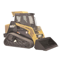
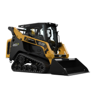
Tie Down Points: The RT-75 / RT-75HD has 4 tie down points (fig. 6.1-1 and 6.1-
2, items A and B). Tie down points “A” are to be used ONLY for securing the
machine to a trailer during transport.
Tie down points “A” are NOT to be used as anchor points for lifting, moving or
retrieving the machine in any way, nor are they to be used to lift, move or extract
objects of any kind, in any way.
Note: Points B (fig. 6.1-2) serve multiple purposes (see also sections 6.1 - 6.5).
Any use of the machine tie down points varying from that described in this
manual shall be regarded as unintended or improper use. The supplier cannot be
held responsible for any damage resulting from improper use. This risk is borne
solely by the user.
6.2-1 Tie Down Guidelines
Below are guidelines that must be followed when tying the machine down for
transport. Chains must not contact the bucket or other attachment while in use
for tie down purposes.
Front Tie Down Points (see figure 6.2-1)
When securing the machine at the front using tie town points “A” (fig. 6.1-1),
chains must extend forward a minimum of 18” from points “A” on either side of
the machine with a minimum chain length of 43”. For rail and sea transport, the
chains may only extend forward 30” from points “A” (max. chain length of 47.4”).
For road transport only, they may extend forward 42” from points “A” (max. chain
length of 57.4”).
Rear Tie Down Points (see figure 6.2-1)
When securing the machine at the rear using tie down points “B” (fig. 6.1-2),
chains must extend rearward a minimum of 25.65” from points “B” on either side
of the machine with a minimum chain length of 80” (crossed) or 38.7” (not
crossed).
6.3 Towing / Retrieving the RT-75 / RT-75HD
In the event that the RT-75 / RT-75HD needs to be towed or retrieved, it will not
roll freely. You must drag it to safety. Use only chains that are rated for pulling a
machine of this size and weight. Attach these chains to BOTH multi purpose
anchor points (items B, fig. 6.1-2) at the rear of the machine.
Note: When connected, chains should be attached so that they extend straight
backward from points “B” (fig. 6.1-2) and must remain within 20° of the
original position (in all directions) throughout the retrieval process (fig. 6.3-1).
Once secure, pull the machine from the rear ONLY. If possible, drag the machine
onto a trailer, then secure and transport.
RT-75 / RT-75HD US O&M
0405-073 2020-07