5 OPERATION
88
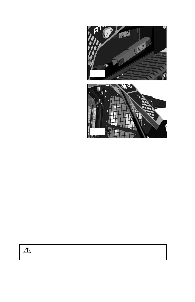
5.14 Lift Arm Brace
When the lift arms must be left in
the raised position, the lift arm
brace must be engaged.
To install:
1. Lower the lift arms, stop and
remove any attachments and
park the machine on firm and
level ground.
2. Have an assistant withdraw
the retaining pins from the lift
arm brace (on the fender) and
remove the brace, then stand
clear.
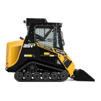
3. Raise the lift arms to the
upper limit to allow for brace
installation.
4. Have the assistant place the lift arm brace onto the top side of the cylinder
ram and install the retaining pins to secure it there, then stand clear.
5. Slowly lower the lift arms until they come to rest on the brace.
To remove:
1. Raise the lift arms until they are clear of the brace.
2. Have an assistant withdraw the retaining pins and remove the brace from
the cylinder, then stand clear.
3. Lower the lift arms to the lower stop.
4. Have the assistant position the lift arm brace over the lift arm brackets on
the fender and install the retaining pins to secure it there.
Do not go beneath unsecured lift arms. Always install the lift arm brace
prior to going beneath the lift arms while raised.
RT-75 / RT-75HD US O&M
0405-073 2020-07
5.14-1
5.14-2