19
8. External Output
WARNING
◇ When connecting or disconnecting the Recorder Output Cable or
RS-232C Cable to the instrument, be sure to turn off the power
(DC24V). If AD-32 (AD-33 or AD-34) is used, be sure to remove the
plug from the outlet before connecting these cables.
The instrument comes equipped with external outputs for a 4 to 20mA recorder and a
RS-232C.
(1) Recorder output
The Recorder Output provides a 4 to 20mA signal (open-circuit voltage is approx. 24V) of the
DMF(%) and temperature (-15.5 to -160.5℃).
The DMF(%) range to be output through the 4 to 20mA signal is set as described in Chapter 15
"Setting the Recorder Output." (See page 30.)
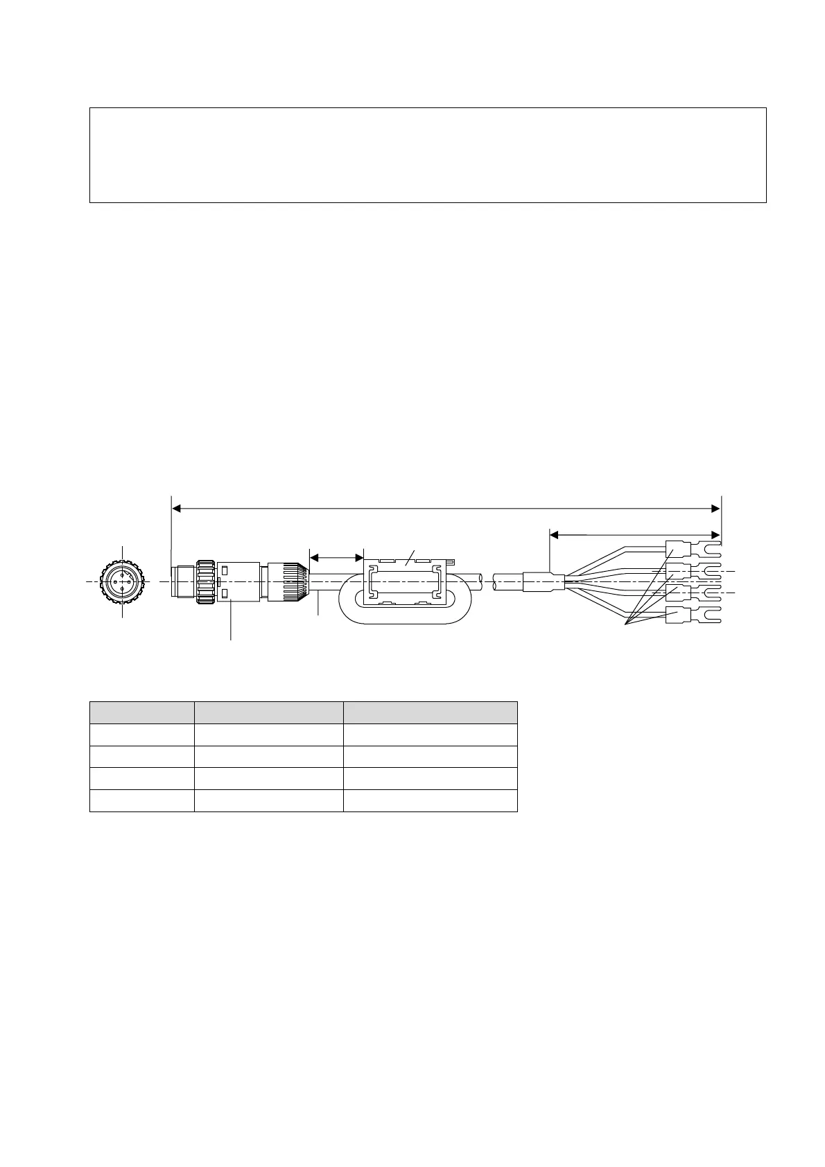
To utilize the 4 to 20mA signal, connect the Recorder Output Cable (optional) to the Recorder
Output terminal on the main unit.
Recorder output cable and code table
Fig. 8-1
Pin No. Code color Polarity
1 Red DMF(%) +
2 Red/White DMF(%) -
3 Black Temperature +
4 Black/White Temperature -
Approx. 2cm
Length: 5m/10m/15m/ 20m
Approx. 6cm
Clamp filter
Corner tip open terminal
1
2
3
4
Cable
Waterproof connector plug

 Loading...