30
15. Setting the Recorder Output
The instrument can output a DC 4 to 20mA signal across a specified range of DMF(%). The
upper and lower limit values can be set.
The lower limit value of DMF(%) should be set in the range of -2.0 to 39.5%.
The upper limit value of DMF(%) should be set in the range of -1.0 to 40.5%.
The difference between the upper and lower limit values should be greater than 1.0%.
For example, to output the DMF(%) value of 0.0 to 20.0% at DC 4 to 20mA, set the lower limit
value to 0.0 and the upper limit value to 20.0.
● Setting procedure
① Connect the power according to the
procedure described on page 24,
section "9.Power Supply".
② The current DMF(%) is displayed on the
screen.
If there is no sample on the prism
surface, [LL.L] will be displayed.
③ Press the key for one second.
[t] is displayed.
Press the key again and the display
will change to [0]. Press the key
again to display [3] (Fig. 15-1).
④ Press the key.
The current lower limit value will blink
on the display (Fig. 15-2).
⑤ Adjust the displayed value to the
desired lower limit value by using the
and/or keys (Fig. 15-2).
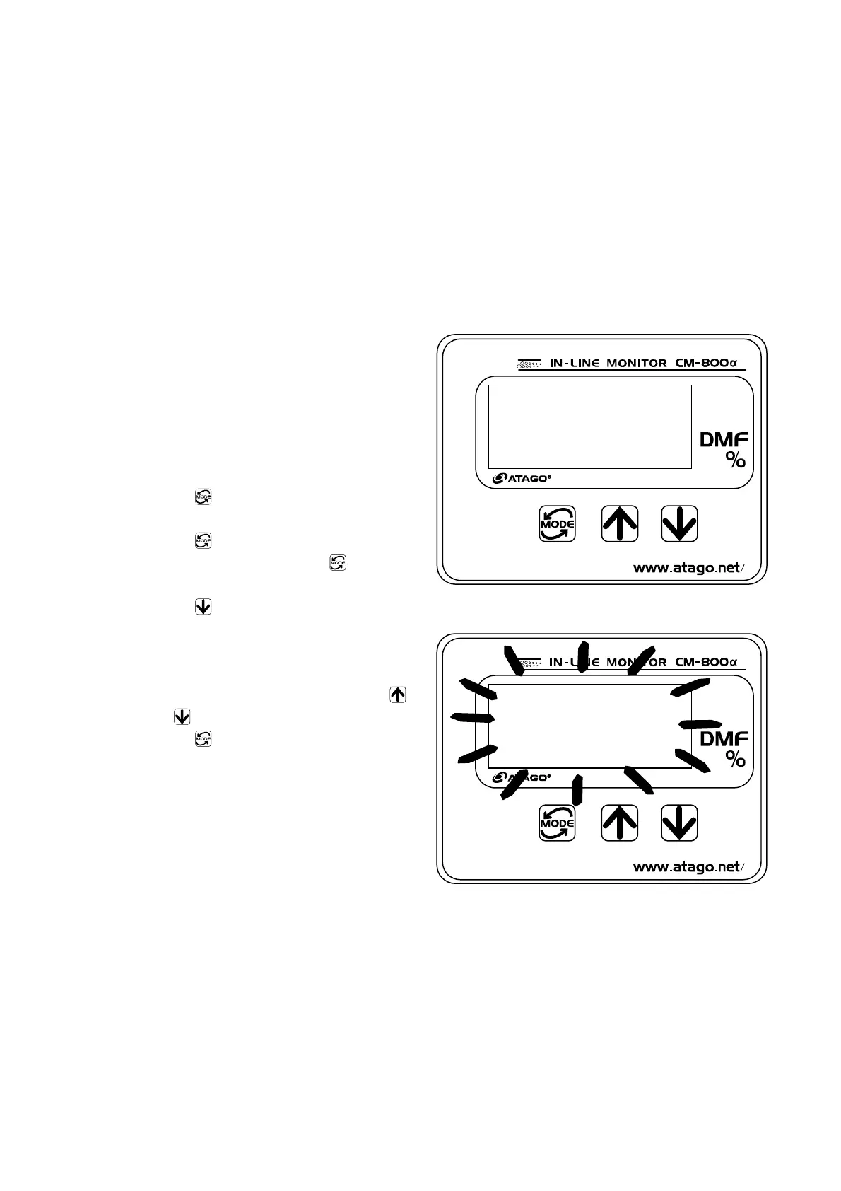
⑥ Press the key.
The lower limit value is now set and the
display returns to [3] (Fig. 15-1).
Fig. 15-1
Example: When the lower limit value of the
recorder output range is set to 0.0%.
Fig. 15-2

 Loading...