31
⑦ Press the key again and the display
turns to [4] (Fig. 15-3).
⑧ Press the key.
The current upper limit value will blink
on the display (Fig. 15-4).
⑨ Adjust the displayed value to the
desired upper limit value by using the
and/or keys.
⑩ Press the key.
The upper limit value is now set and the
display returns to [4] (Fig. 15-3).
⑪ Each time the key is pressed, the
menu item displayed switches in the
order of: [5] and DMF(%).
Select DMF(%).
N If 30 seconds pass when in steps
③ through ⑩ above, the display
returns to the continuous display of
the DMF(%).
m Recorder Output when an error
message is displayed
Please take note of the recorder
output signal when an error
message is displayed on the
instrument unit.
Error
Message
Recorder Output
LL.L 4mA
HH.H 20mA
EE.E 20mA
... Corresponds
displayed DMF(%)
value.
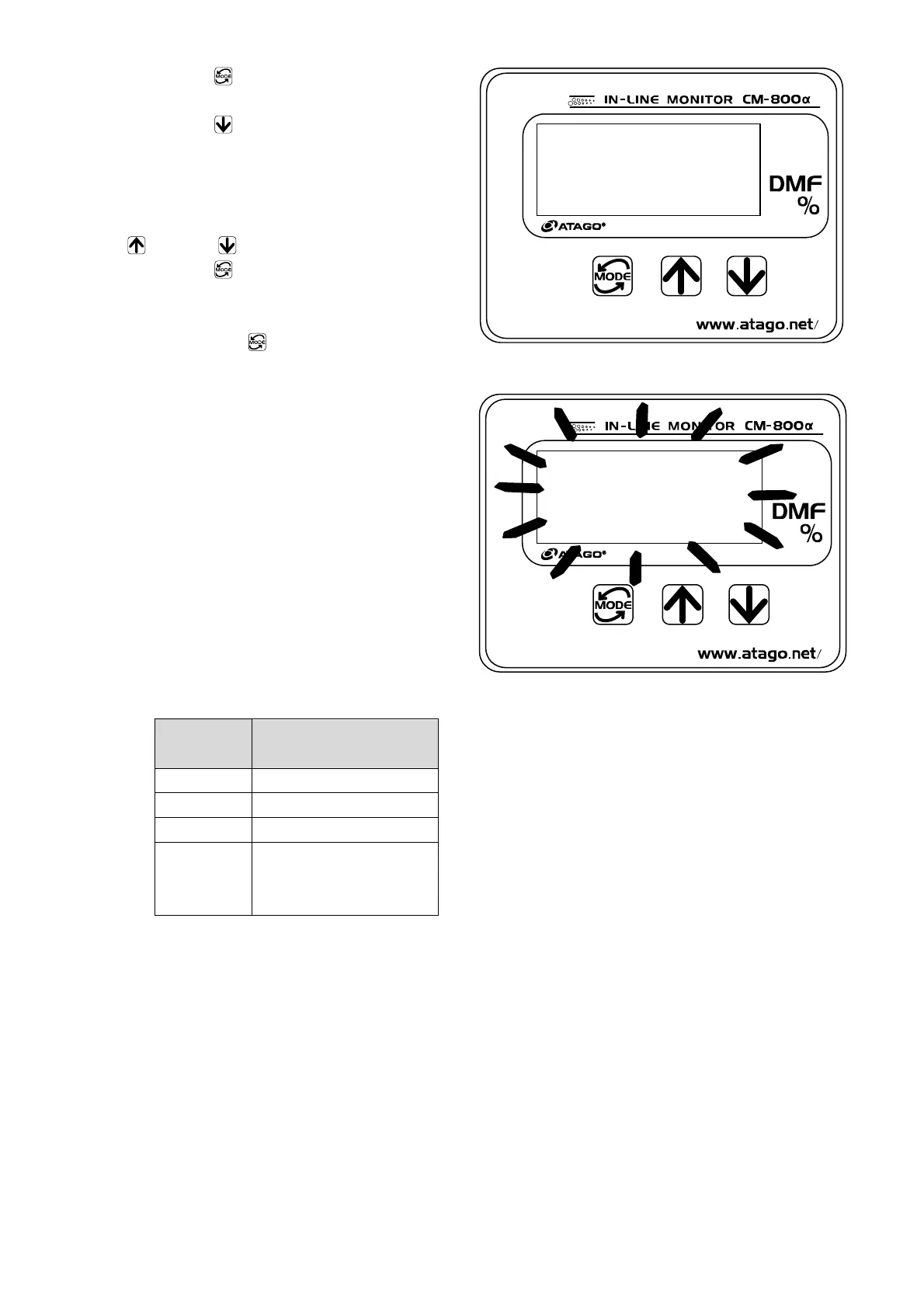
Fig. 15-3
Example: When the upper limit value of the
recorder output range is set to 20.0%.
Fig. 15-4

 Loading...