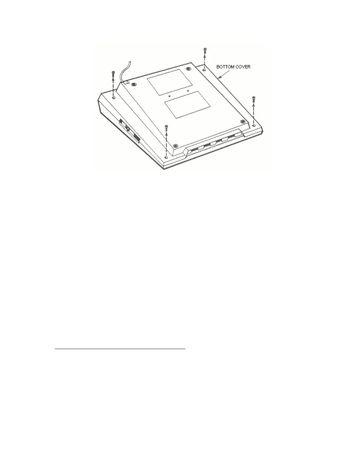
Figure 5-17. 400 Console, Bottom Cover Screw Location
2. Keyboard removal, refer to Figure 5-19
• Remove single Keyboard screw (no. 6 32x1/4)
• Raise left end of Keyboard and disconnect Keyboard Ribbon
Cable
3. Power Supply Removal, refer to Figure 5-20 o Disconnect RF Cable
from Power Supply
• Remove two screws (no. 6 32x3/8) from Power Supply
• Gently pull Power Supply away from casting 1/4 inch and lift
out the Interlock Switch plunger
• Lift Power Supply straight up off the Motherboard connector
pins.
Access to CPU, RAM, and Motherboard:
1. Module Assembly removal, refer to Figure 5-21
• Disconneet and remove Speaker assembly
• Lift Module Assembly out of Bottom Cover
2. CPU and RAM Printed Circuit Board Removal
5-31 System Service Manual