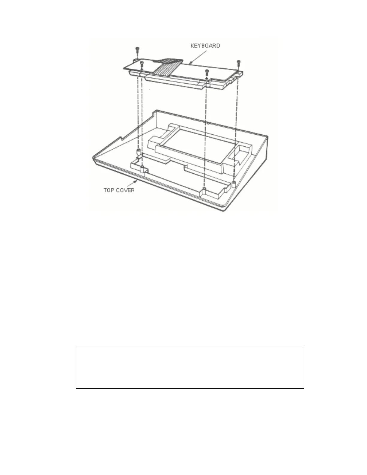
Figure 5-24. 800 Console, Keyboard Removal
5. Access to CPU Printed Circuit Board, refer to Figure 5-27
• Set Module Assembly on its back
• Remove nine screws (no. 6 32x5/8) from Lower Shield
• Lift Motherboard and Lower Shield out of aluminum
casting
• Remove CPU printed circuit board
6. Access to Motherboard, refer to Figure 5-28
• Carefully slide screwdriver underneatn Motherboard next
to nylon clip. Gently raise handle of screwdriver,
prying off. Repeat operation for other three nylon
clips.
• Lift Motherboard off Lower Shield
CAUTION
Be careful not to bend any of the pins on the
Motherboard Connector
5-39 System Service Manual