data on the 400 and 800 Computer Consoles. The 4051 integrated
circuits are analog multiplexers controlled by the input lines A, B,
C and X. A binary count between 0 and 7 is applied to the input lines
A, B, and C (pins 9, 10, and 11) to select one of the output lines,
XO - X7. The eight possible inputs on each 4051 chip allows a maximum
of 64 keys to be scanned (the 400 and 800 keyboards both contain 57
keys). When a key is scanned and found depressed, the output line X
(pin 3) goes low to signal the POKEY chip to stop the count. The
value present on lines K0 through K5 of the POKEY chip is sent to the
microprocessor. The microprocessor uses a "look-up" table to
determine the Keyboard character depressed.
4.3.2.4 Memory Map Decoder. The Memory Map Decoder integrated circuit
(Z103) on the 400 Motherboard is a one-of-ten decoder. Four input
lines (pins 12, 13, 14, and 15) determine which output line is
selected. The 400 Console only uses three of the input lines (pin 12
being grounded) for a total of eight selected output lines (S0 - S7).
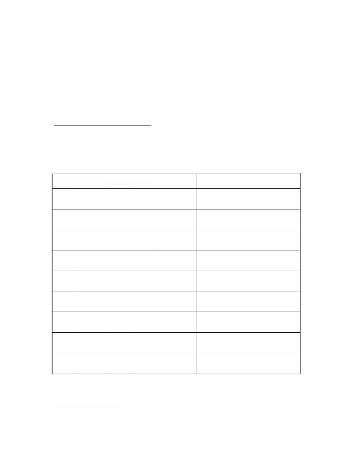
Refer to Table 4-2 for the line selected for each input combination.
TABLE 4-2. Memory Map Select Lines
Signal/Pin
GND12 A15/13
A14/14
A13/15
Active
line
Device
L
L
L
L
1 - S0
8K RAM
L
L
L
H
2 - S1
8K RAM
L
L
H
L
3 - S2
8K RAM
L
L
H
H
4 - S3
8K RAM
L
H
L
L
5 - S4
8K RAM/CARTRIDGE L, R
L
H
L
H
6 - S5
8K RAM/CARTRIDGE L
L
H
H
L
7 - S6
2K ROM
L
H
H
L
7 - S6
I/O DECODER (Z105)
L
H
H
H
9 - S7
4K ROM "E" and "F"
4-12 System Service Manual
4.3.2.5 I/O Decoder. The I/O Decoder integrated circuit (Z105) is a
one-of-eight decoder/demultiplexer. The I/O Decoder is used to select