3. Power Supply installation, refer to Figure 5-20
• Align Power Supply over Motherboard connector pins and
Bottom Cover guide posts and gently press down.
• Install Interlock Switch Plunger into Aluminum Casting.
Make sure the lower end of the Plunger is positioned
over the Interlock switch and the Plunger shaft rides in
its' notch in the Power Supply Heat Sink.
• Install two Power Supply mounting screws (no. 6 32x3/8)
CAUTION
Ensure that the RF Cable is not trapped under the
Module Assembly
• Route the RF Cable through its' slot in the Power Supply
board and plug into Power Supply jack.
Install single Keyboard mounting screw (n o. 6 32x1/4)
4. Top Cover installation, refer to Figures 5-17 and 5-18.
• Open Cartridge Door
• Slide Top Cover down over the open Cartridge Door and
Power-On LED.
• Guide the Top Cover locator pins into the Keyboard holes
and snap the Top Cover hook under the Keyboard.
• Close the Cartridge Door and set system on its' back
• Align Top and Bottom Covers and install four screws (no.
6 20x1/2) into Bottom Cover.
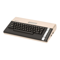
5.8 ASSEMBLY, 800 COMPUTER CONSOLE
The following paragraphs detail the procedures required to re-
assemble the 800 Computer Console and its' associated printed circuit
boards.
1. Keyboard installat.ion~ refer to Figure 5-24
• Lay Top Cover on its' back with Keyboard in Top Cover o
Install four mounting sCrews (no. 6 32x5/8)
5-43 System Service Manual