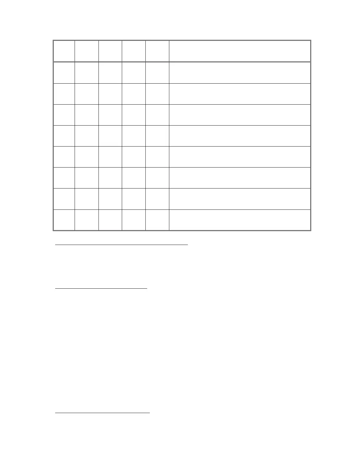
RS0
RS1
RwW
CRA2
CRB2
Function
0
0
X
0
X
Read or Write Data Direction
Register A
0
0
0
1
X
Write into Peripheral interface
Register A
0
0
1
1
X
Read from A-side input pins PA0 -
PA7
0
1
X
X
X
Read or Write Control Register A
1
0
0
X
1
Write into Peripheral Interface
Register B
1
0
X
X
0
Read or Write Data Direction
Register B
1
0
1
X
1
Read from B-side input pins PB0-
PB7
1
1
X
X
X
Read or Write Control Register B
IRQA - IRQB Interrupt Requests. These lines connect to the
microprocessor IRQ line to provide interrupt requests. The IRQ lines
are open-collector so that several can be connected together to the
same input. When the PIA chip wants to communicate with the
microprocessor this line is set low. Control of the IRQ lines is
determined by the Control Registers A and B.
CA1 - CA2 Control lines. CAl and CA2 are the control lines for the
peripheral devices. CA1 is an input interrupt only from an I/O
device. The interrupt can be set by a negative or positive transition
of the input signal as determined by the Control Register A. Setting
the interrupt request line IRQA by CA1 is also controlled by CRA. CA2
can be used either as an input or output control line. In one output
mode CA2 generates a pulse each time data is read by the processor.
The pulse can be used to input sequential data. In a second output
mode CA2 is used in conjunction with CA1 to provide the "handshake"
between the microprocessor and the peripheral device. The CA1 input
is used to interrupt the microprocessor to indicate that data from a
peripheral device is available. When the processor has finished
reading the available data the CA2 output line is set low to signal
the peripheral device that new data can be made available.
4-10 System Service Manual
CB1, CB2 Control Lines. CB1 and CB2 are peripheral device control
lines. CB1 is used as an input control line only. CB1 control line
can set IRQB on a negative or positive transistion as determined by