35
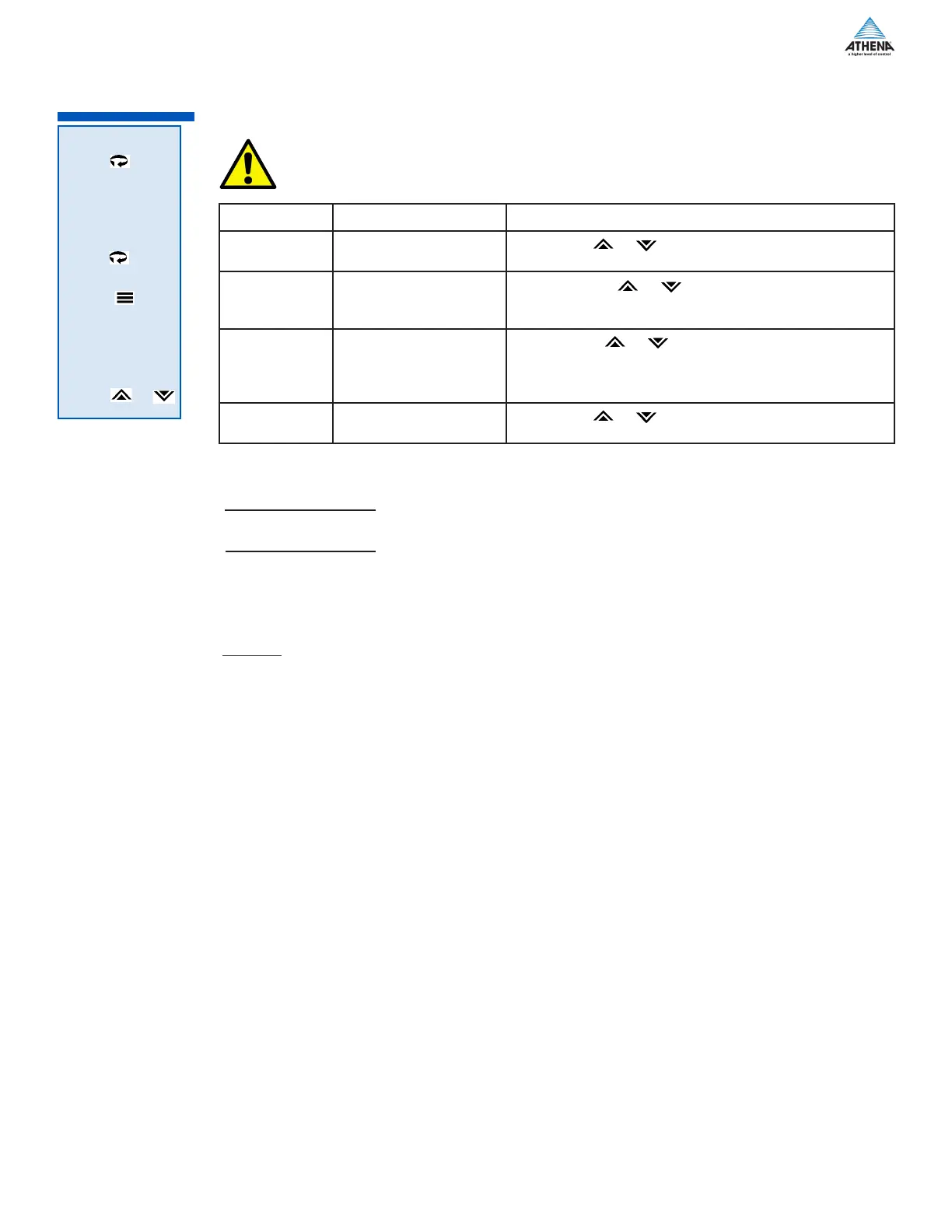
Display Parameter Available Selections
Id.no
1 - Use the or keys to select the id value of the
controller ... value must be between 1 and 255
bAUD
Baud rate
2400 - Use the or keys to select the
communications baud rate. Available rates include 300, 600,
1200, 2400,4800, 9600
dAt.F
Data format
8n1 - Use the or keys to select the format of the
data to be transferred (data, parity and stop bits) ... Available
formats are 7.o1, 7.E.1, 7n2, 7o2, 7E2, 8n1, 8o1, 8E1,
8n2
tr.dL
Transmit delay
1 - Use the or keys to select the delay in
transmitting data ... value must be between 1 and 100 ms
FACt
SERL
Id.no
Operation
RS-232 - This method allows bidirectional data transfer via a three-conductor cable consisting of signal
ground, receive input and transmit output. It is recommended for communication distances less than 50 feet
between the computer terminal and the instrument. Note: Multiple instruments cannot be connected to the
same port.
The RS232 port is optically isolated to eliminate ground loop problems. Typically, “Data Out” of the computer/
terminal connects to the “RCV” terminal. “Data In” connects to the “XMT” terminal. If shielded cable is used,
it should be connected to the frame ground at one end only. Signal ground is to be connected at appropriate
ground terminals (refer to wiring diagram on next page).
RS-485 - The RS485 multipoint capability allows up to 32 controllers to be connected together in a half-du-
plex network or up to 100 controllers with an appropriate communications repeater. This method allows bidi-
rectional data transfer over a twisted pair cable. The twisted pair cable is a transmission line; therefore, termi-
nating resistors are required at the most distant ends of the line to minimize reflections (typically 120 ohms at
each end). The RS485 circuit is fully optically isolated, eliminating ground loop problems. Parallel drops from
the transmission lines should be kept as short as possible; however, the line may be daisy-chained at each
controller. The polarity of the line is important and each device will specify an “A” (+) and “B” (-) connection.
Use the menu above to set the communication parameters and establish how the controller ‘talks’ to other
devices.
Please refer seperate for details on software protocols that allow the controller to
be queried and modified remotely.
30 Provides a one-to-one connection between the controller and an RS-232 port.
Computers, PLCs, or dumb terminals may be used to set and access controller data.
Provides one-to-many communications. If run exceeds 1000 ft., terminate the
controller furthest from the computer by connecting a 120-ohm, 1/4-watt resistor between terminals 13 and
14.
*Converter is supplied with a wallplug-mount power transformer.
 Loading...