5
IMPORTANT: All electrical wiring connections should be made only by trained personnel, and in strict accordance
with the National Electrical Code and local regulations.
The Series C controller has built-in circuitry to reduce the effects of electrical noise (RFI) from various sources.
However, power and signal wires should always be kept separate. We recommend separating connecting wires
into bundles: power; signal; alarms; and outputs. These bundles should then be routed through individual conduits.
Shielded sensor cables should always be terminated at one end only.
If additional RFI attenuation is required, noise suppression devices such as an R.C. snubber at the external noise
source may be used. If you wish, you may order this suppressor directly from Athena, part number 235Z005U01.
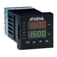
Figure 4. Contact Identification
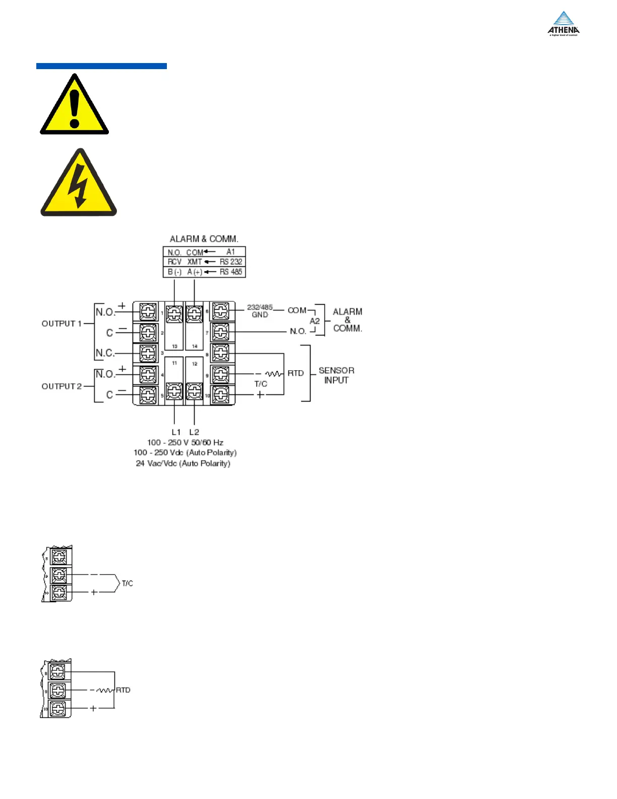
Make sure that you are using the appropriate thermocouple and extension wire. Connect the negative lead
(generally colored red in ISA-type thermocouples) to contact #9; connect the positive lead to contact #10.
Extension wires must be the same polarity as the thermocouple.
Figure 5. Thermocouple Input Wiring
Note: For 2-Wire RTD
Jumper 8 & 10
The Series C accepts input from 2- or 3-wire, 100 ohm platinum resistance temperaure detectors (RTDs).
Connect 2-wire RTDs to contacts #9 and #10, with a jumper across contacts #8 and #10. Keep leads short and
use heavy gauge copper extension wire, if necessary, to minimize lead resistance. For long runs, 3-wire RTDs
should be used.
Figure 6. RTD Wiring
 Loading...