13
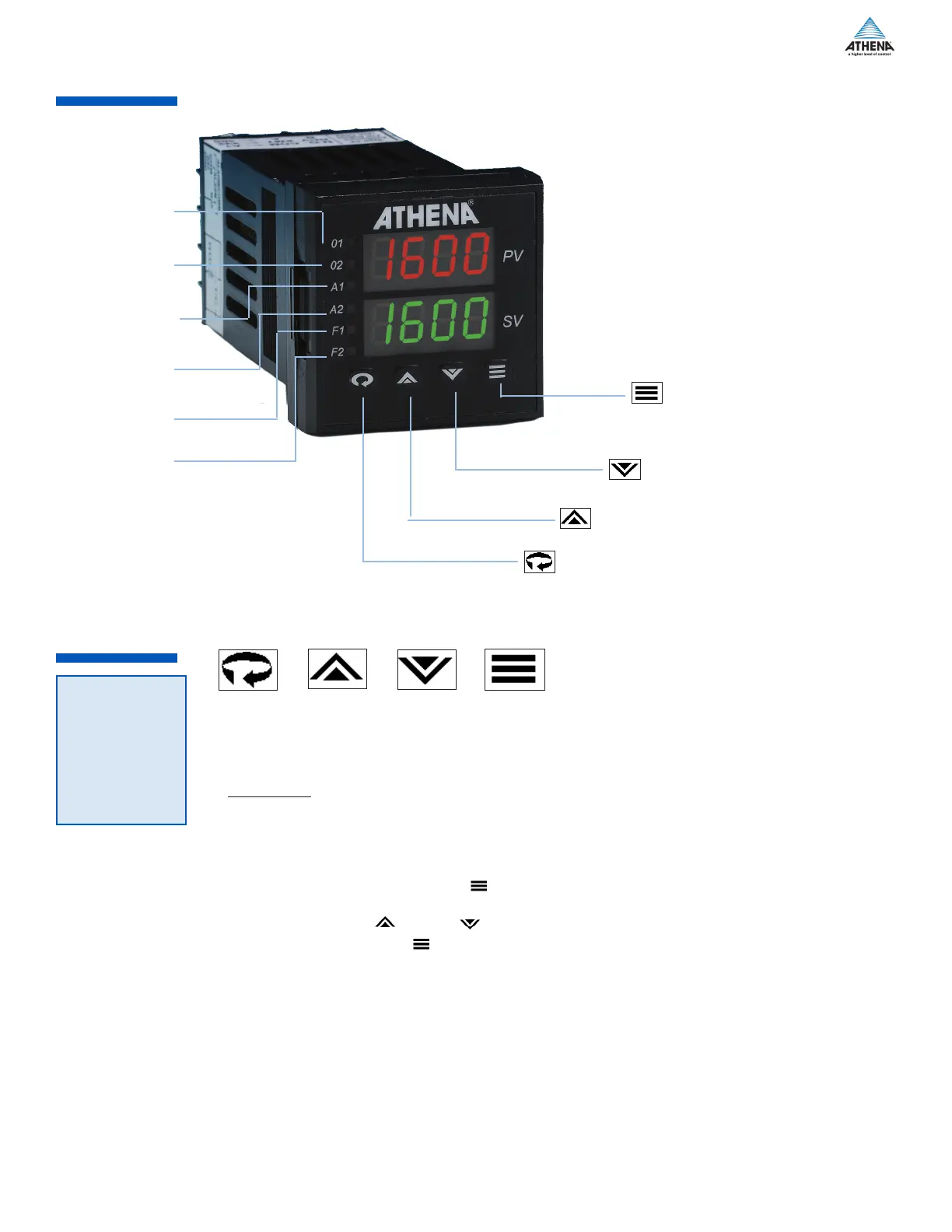
Mode/Enter Key
Used to enter Parameter selections,
access operating modes, release
latched alarms, and index through
menu items.
Lower Key
Used to decrease values.
(Hold for fast-step progression)
Raise Key
Used to increase values.
(Hold for fast-step progression)
Menu Access Key
Used to enter or exit the menu system, index to the next
menu, and enter the Security Level menu.
Figure 19. Front Panel Controls and Indicators
When power is first applied to the Series C, all segments of the LED displays will be momentarily
illuminated while the instrument goes through a series of diagnostic checks to verify proper operation. A
software version number will then appear in the lower display, followed by a configuration code (upper
display) and the communications protocol which is supported (lower display).
IMPORTANT: On initial startup, there is a possibility that outputs may be activated. We recommend
placing the unit in Standby mode until you have configured the controller according to your application
requirements.
To place the controller in Standby, follow this procedure:
1) Press and hold Mode/Enter key until a menu label appears in upper display (approximately
three seconds).
2) Press Raise or Lower key until
Stby
appears in the lower display.
3) Press Mode/Enter key. (The upper display will alternate between
Stby
and process value.)
Operations Overview
The user interface of the Series C allows you to use menus to set up the instrument, set the desired
security level, change the setpoint, and conveniently change operating modes. A functional representation
of the user interface and the key presses necessary to perform the basic functions is shown for each menu
throughout these instructions.
Security Level,
Output 1
LED indication
of Heat cycle
(Output 1 action)
Output 2
LED indication
of Cool cycle
(Output 2 action)
Alarm 1
LED indication
of Alarm1 condition
Alarm 2
LED indication
of Alarm 2 condition
Function 1
LED indication of
Special Function 1
Function 2
LED indication of
Special Function 2
 Loading...