Manual, F/T Sensor, Ethernet Axia
Document #9610-05-Ethernet Axia-09
Pinnacle Park • 1031 Goodworth Drive • Apex, NC 27539 • Tel:+1 919.772.0115 • Fax:+1 919.772.8259 • www.ati-ia.com
38
4.9 Diagnostic Monitoring
During operation, the Ethernet Axia rmware monitors the hardware. When the user applies power to the
sensor, the rmware waits (5) seconds before evaluating the supply voltage for errors. Status messages are in
the following table.
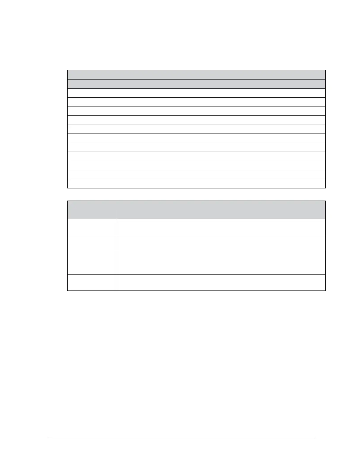
Table 4.10—Status Messages During Monitoring
Message
Supply Voltage out of range
Gage Temperature out of range
Calibration checksum error
Gage(s)disconnected:<list>
Gage(s)out-of-range:<list>
Force/torque out of range
Common error
Simulated error
Monitor condition latched
Error(unspecied)
Good(nostatuscodeerrors)
System health indicators that the Axia F/T rmware monitors are in the following table.
Table 4.11—Network Health System
Indicator Description
Stack Usage
The maximum amount of the stack usage is continuously monitored. An error
message is generated if the available stack is too low.
MCU Program
Memory CRC
TheCRCoftheMCUprogramashmemoryiscontinuouslymonitored.An
error message is generated, if an error is found.
Parameter
Memory CRC
The CRC of the MCU RAM Parameter Memory, which is used to store the
calibration, is continuously monitored. An error message is generated, if an
error is found.
MCU Data
Memory Test
TheMCUDataMemory(RAM)iscontinuouslytested.Anerrormessageis
generated, if an error is found.

 Loading...