Manual, F/T Sensor, Ethernet Axia
Document #9610-05-Ethernet Axia-09
Pinnacle Park • 1031 Goodworth Drive • Apex, NC 27539 • Tel:+1 919.772.0115 • Fax:+1 919.772.8259 • www.ati-ia.com
51
Output Code: When this statement’s comparison is found true, this 8-bit value will be bitwise
OR’ed with the Output Code values of all other true statements to form the
threshold output. Any set bits remain latched until the user issues a Resent Latch.
If no statements are true the threshold output is zero.
The value displays in hexadecimal, format 0x00. A user may type output codes
in hexadecimal format or in decimal. Bit pattern representing each thresholding
statement number are in the following table.
Table 6.3—Bit Patterns for Thresholds Breached
#: Bit Pattern #: Bit Pattern #: Bit Pattern #: Bit Pattern
0: 0x00000001 4: 0x00000010 8: 0x00000100 12: 0x00001000
1: 0x00000002 5: 0x00000020 9: 0x00000200 13: 0x00002000
2: 0x00000004 6: 0x00000040 10: 0x00000400 14: 0x00004000
3: 0x00000008 7: 0x00000080 11: 0x00000800 15: 0x00008000
Get Statuses: Click the Get Statuses button to update the static display of the threshold status. If
a threshold is unsatised, the threshold numbers are crossed out.
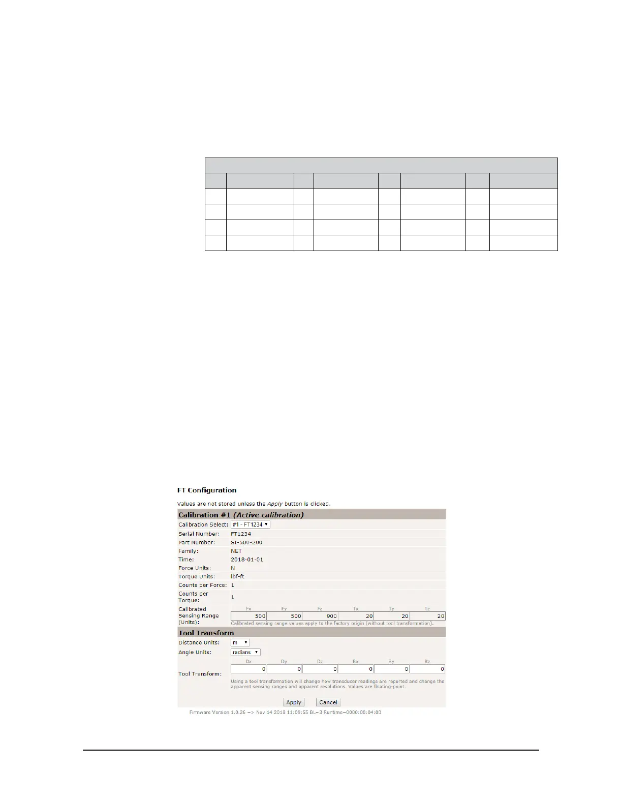
6.6 F/T CongurationsPage(cong.htm)
On the Congurations page, a user may select the active calibration (Section 15.3—Calibration Ranges)
and tool transformation settings for the sensor system. When the user clicks the Apply button, the changes
on this page are implemented on the sensor. For more information about tool transformation feature, refer to
Section 4.7—Tool Transformation.
From the Congurations page, a user may obtain the following values: the sensor’s Serial Number, Part
Number, calibration Family, Time or date the sensor was calibrated, force units, torque units, counts per
force, and counts per torque. Note that these are the same values that are in Section 8.4—Console “CAL” |
“SET” Command Fields and Values and Section11.2—CalibrationInformation(netftcalapi.xml).
For more information about how F/T values are scaled with the counts per force and counts per torque, refer
to Section 4.4—Converting Counts Per Force/Torque to F/T Values.
The Calibrated Sensing Range eld displays the maximum rating for each axis of the selected calibration.
Figure 6.7—CongurationsPage

 Loading...