- 75 -
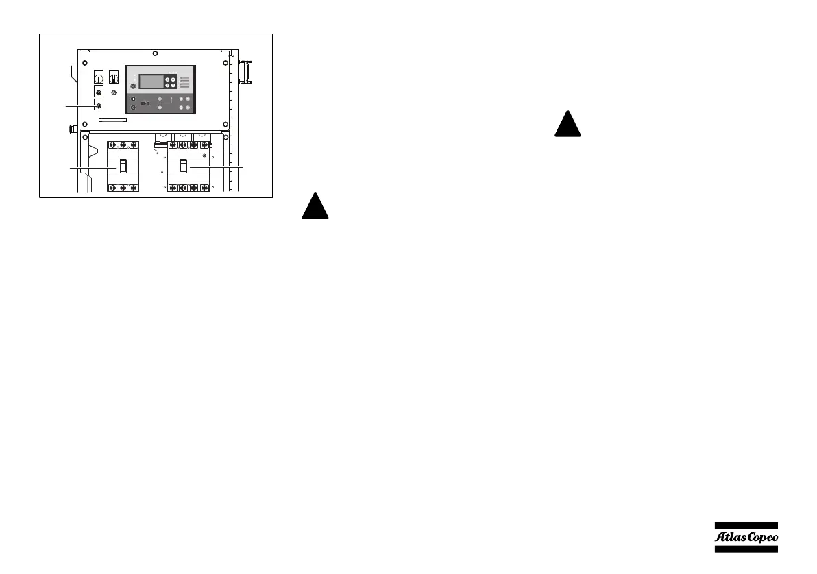
Q1.1....Circuit breaker for low voltage, high
current
Interrupts the low voltage power supply
towards X1 when a short-circuit occurs at
the load side or when the overcurrent
protection (1 phase - 3 phase: 175 A /
3 phase - 3 phase: 152 A) is activated. It
must be reset manually after eliminating the
problem.
Q1.2 ....Circuit breaker for high voltage, low
current
Interrupts the high voltage power supply
towards X1 when a short-circuit occurs at
the load side or when the overcurrent
protection (100 A) is activated. It must be
reset manually after eliminating the
problem.
R12 .....Voltage adjustment
Allows to adjust the output voltage.
Depending on which mode the generator is running
in, circuit breaker Q1.1 or Q1.2 will be operational.
Circuit breakers Q1.1 and Q1.2 cannot be switched on
at the same time. This is prevented by means of the
auxiliary voltage selection relays K11 and K12 (refer
to circuit diagram 9822 0996 11/01) or S10b and S10c
(refer to circuit diagram 9822 0996 12/01).
The selection between the two modes is done by
means of S10.
S10......Output voltage selection switch
Allows to select a 3 phase high output
voltage or a 1 phase / 3 phase low output
voltage. Selector switch S10 is located on
the alternator.
R12
Q1.2
Q1.1
AMF operation is not possible with a
dual voltage generator.
Changing the output voltage is only
allowed when the unit has stopped.
After changing the output voltage by
means of the selection switch S10,
adjust the output voltage by means of
potentiometer R12 to the required
value.
 Loading...


