- 77 -
9.3.11 IT-relay
The generator is wired for an IT network i.e. no
supply lines of the power supply are directly earthed.
A failure in insulation resulting in a too low insulation
resistance, is detected by the insulation monitoring
relay.
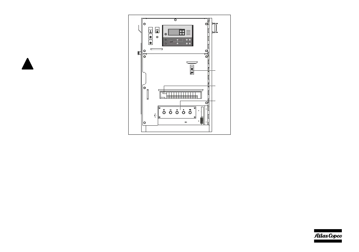
Q1 .......Circuit breaker for X1
Interrupts the power supply X1 when a
short-circuit occurs at the load side, or when
the overcurrent protection is activated.
When tripped, Q1 interrupts the three phases
towards X1. It must be reset manually after
eliminating the problem.
X1 .......Main power supply (400 Vac)
Terminals L1, L2, L3, N (= neutral) and PE
(= earthing), hidden behind the control panel
door and behind a small transparent door.
N14 .....Insulation monitoring relay
Checks the insulation resistance and
activates Q1 when the insulation resistance
is too low.
S2........Emergency stop button
Push the button to stop the generator in case
of an emergency. When the button is
pressed, it must be unlocked, by turning it
anti-clockwise, before the generator can be
restarted. The emergency stop button can be
secured in the locked position with the key,
to avoid unauthorized use.
The generator shall not be operated
with other networks (such as TT or
TN). Doing so will cause tripping of
the insulation monitoring relay.
The generator is wired for an IT
network i.e. no supply lines of the
power supply are directly earthed.
A failure in insulation resulting in
too low an insulation resistance, is
detected by the insulation
monitoring relay.
At each start-up and any time a new
load is connected, the insulation
resistance must be verified. Check
for the correct setting of the
insulation monitoring relay (factory
set at 13 kΩ).
X1
N14
Q1
 Loading...


