Sx
FxFx Fx
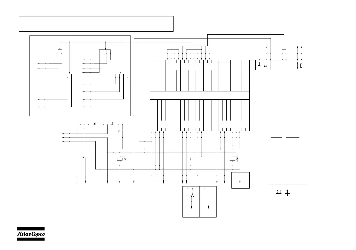
to Circ.Diagr POWER
Current Transfo
T1-T3
c8
140
c8
143
c8
142
c8
141
Circ.Diagr POWER
Fuses
F1-F3
a6
124
a0
127
a0
126
a0
125
a0
125
a0
126
a6
124
a0
127
c8
140
c8
141
c8
143
c8
142
to Circ.Diagr POWER
a6
12
a3
5
a2
13
c2
1
c2
1
a2
13
c2
3
c2
1
a3
11
a6
12
a2
17
a6
12
a3
5
a3
5
a3
5
a6
12
a6
12
a6
12
a2
17
a2
17
a3
15
a3
5
a3
14
a6
12
a3
14
a3
18
a3
26
a3
11
a3
a0
38
a0
447
a0
127
a0
125
a0
126
a6
124
c8
140
c8
140
c8
140
c8
141
c8
143
c8
142
a3
6
a3
7
a3
4
a3
6
a3
7
S2a
1
X25
bx = 1.5 mm² NSGAFOeU
l = 95 mm²
lx = 95 mm² EPR-CSP (BS6195-4C)
k = 70 mm²
j = 50 mm²
i = 35 mm²
54= green/yellow
1 = brown
Wire size: Colour code:
Legend
a = 1 mm²
b = 1.5 mm²
c = 2.5 mm²
d = 4 mm²
e = 6 mm²
f = 10 mm²²
g = 16 mm
h = 25 mm²
0 = black
2 = red
3 = orange
4 = yellow
5 = green
6 = blue
7 = purple
8 = grey
9 = white
to Circ.Diagr POWER
a6
12
Sx=Remote
Start/Stop-switch
a0
38
a0
447
PE
X25
5
4
3
1
2
PE
14
a3
A1
A1
X10
A3
A3
X10
A5
A5
X10
C3
C3
X10
A4
A4
X10
C1
C1
X10
B2
B2
B1
B1
X10
C4
C4
X10
10A
F10
K5
S20
14
a3
a2
17
a6
12
a6
12
a3
18
X25
to A1.15
X25 X25
6
b6
541
b0
542
(see Instruction Manual)
Customer's Installation
MAINS SUPPLY (1P+N)
L1N
6A 6A
(*)
B4
X10
B4
a3
22
Voltage free
contact
a6
12
K4
a3
2
K4
a2
13
c2
1
Note: with dedicated 60Hz-cubicles,
DO NOT connect wire 12/a6 to X10.C4
60Hz
a6
12
C4
C4
X10
(0)
Dual Frequency
a6
12
a3
26
C4
C4
X10
(0)
60Hz
50Hz
S12
a3
26
a6
12
50Hz
(0)
e2
K5
e2
Position of Relay Contacts
C2
C2
X10
e6
K4
to Circ.Diagr POWER
Current Transfo
T1
c8
140
c8
143
Circ.Diagr POWER
Fuses
F1
a0
126
125
a0
125
a0
126
c8
140
c8
143
a0
Single phase 3 phase
a6
12
C5
C5
X10
a3
5
a3
4
K5
Central Alarm Horn
Qc 1103
2nd Parameter
NO
Com
NO
NO
Spare
Input
Input
Input
Input
Input
Input
6
A1
212015 24 252322521 26 27
0 Vdc (Batt-)
14131110 161278 17
High Coolant Temperature
Spare Output
Low Oil Pressure
Remote Start
NO
Com
Com
NO
Start Relay Output
Fuel Control Relay
Preheat Relay
Common for Relay Outputs
Common for VDO-inputs (0 Vdc)
Input
GND
Input
Oil Pressure (VDO)
W/L -Input D+
Coolant Temp (VDO)
Fuel Level (4-20mA)
Input
Input
Magnetic Pick-up (Tacho)
12/24 Vdc (Batt+)
s1
s2
Generator Current Transfo L3
s1
s2
Generator Current Transfo L2
s1
s2
36 3833 34 39 40 4241 43 44
Generator Voltage L1
Generator Voltage L3
Generator Voltage L2
Generator Voltage Neutral
Generator Current Transfo L1
47 484645
Spare output
NO
Com
Generator Contactor
NC
Com
54
CAN-L
CAN-H
GND
Engine CAN-bus Interface
53
55
 Loading...


