199
7679H–CAN–08/08
AT90CAN32/64/128
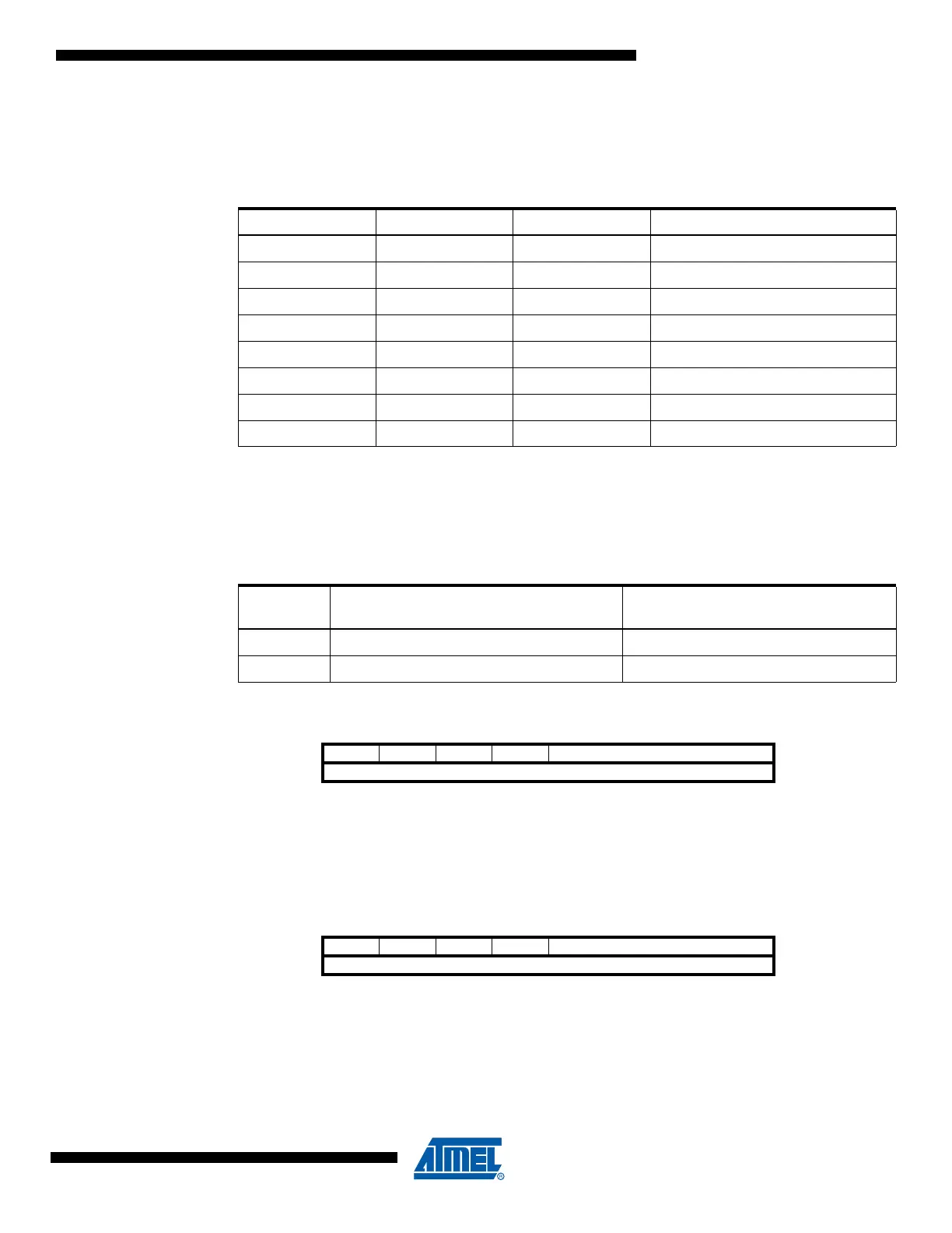
• Bit 2:1 – UCSZn1:0: Character Size
The UCSZn1:0 bits combined with the UCSZn2 bit in UCSRnB sets the number of data bits
(Character SiZe) in a frame the Receiver and Transmitter use.
• Bit 0 – UCPOLn: Clock Polarity
This bit is used for synchronous mode only. Write this bit to zero when asynchronous mode is
used. The UCPOLn bit sets the relationship between data output change and data input sample,
and the synchronous clock (XCKn).
17.11.9 USART0 Baud Rate Registers – UBRR0L and UBRR0H
17.11.10 USART1 Baud Rate Registers – UBRR1L and UBRR1H
Table 17-7. UCSZn Bits Settings
UCSZn2 UCSZn1 UCSZn0 Character Size
0005-bit
0016-bit
0107-bit
0118-bit
100Reserved
101Reserved
110Reserved
1119-bit
Table 17-8. UCPOLn Bit Settings
UCPOLn
Transmitted Data Changed
(Output of TxDn Pin)
Received Data Sampled
(Input on RxDn Pin)
0 Rising XCK Edge Falling XCK Edge
1 Falling XCK Edge Rising XCK Edge
Bit 151413121110 9 8
– – – – UBRR0[11:8] UBRR0H
UBRR0[7:0] UBRR0L
76543210
Read/Write R R R R R/W R/W R/W R/W
R/W R/W R/W R/W R/W R/W R/W R/W
Initial Value00000000
00000000
Bit 151413121110 9 8
– – – – UBRR1[11:8] UBRR1H
UBRR1[7:0] UBRR1L
76543210
Read/Write R R R R R/W R/W R/W R/W
R/W R/W R/W R/W R/W R/W R/W R/W
Initial Value00000000
00000000

 Loading...


