INSTALLATION
5. Installation
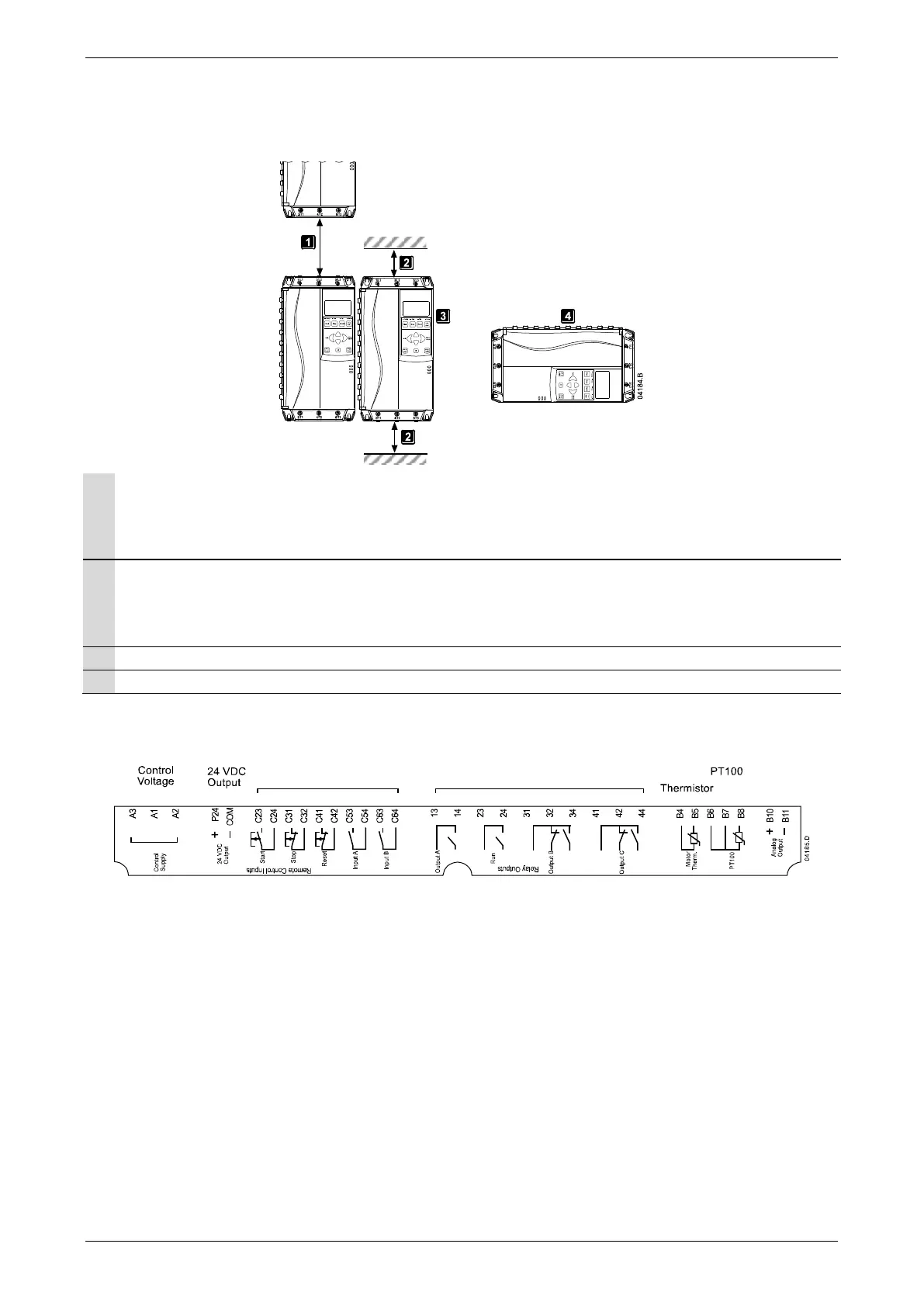
5.1 Physical Installation
EMX3-0023B ~ EMX3-0220B: Allow 100 mm (3.94 inches) between soft starters.
EMX3-0255B ~ EMX3-1000B: Allow 200 mm (7.88 inches) between soft starters.
EMX3-0255C: Allow 100 mm (3.94 inches) between soft starters.
EMX3-0360C ~ EMX3-1600C: Allow 200 mm (7.88 inches) between soft starters.
EMX3-0023B ~ EMX3-0220B: Allow 50 mm (1.97 inches) between the soft starter and solid surfaces.
EMX3-0255B ~ EMX3-1000B: Allow 200 mm (7.88 inches) between the soft starter and solid surfaces.
EMX3-0255C: Allow 100 mm (3.94 inches) between the soft starter and solid surfaces.
EMX3-0360C ~ EMX3-1600C: Allow 200 mm (7.88 inches) between the soft starter and solid surfaces.
Soft starters may be mounted side by side with no clearance (that is, if mounted without communications modules).
The soft starter may be mounted on its side. Derate the soft starter's rated current by 15%.
5.2 Control Terminals
Control terminations use 2.5mm
2
plug-in terminal blocks. Unplug each block, complete the wiring, then reinsert the block.
Remote Control Inputs Relay Outputs
Analog
Output
5.3 Control Voltage
Different models require control voltage to different terminals:
• C1 (110~210 VAC) A1, A2
• C1 (220~440 VAC) A2, A3
• C2 (24 VAC/VDC) A1, A3
User Manual (710-04840-00M) | 9