INSTALLATION
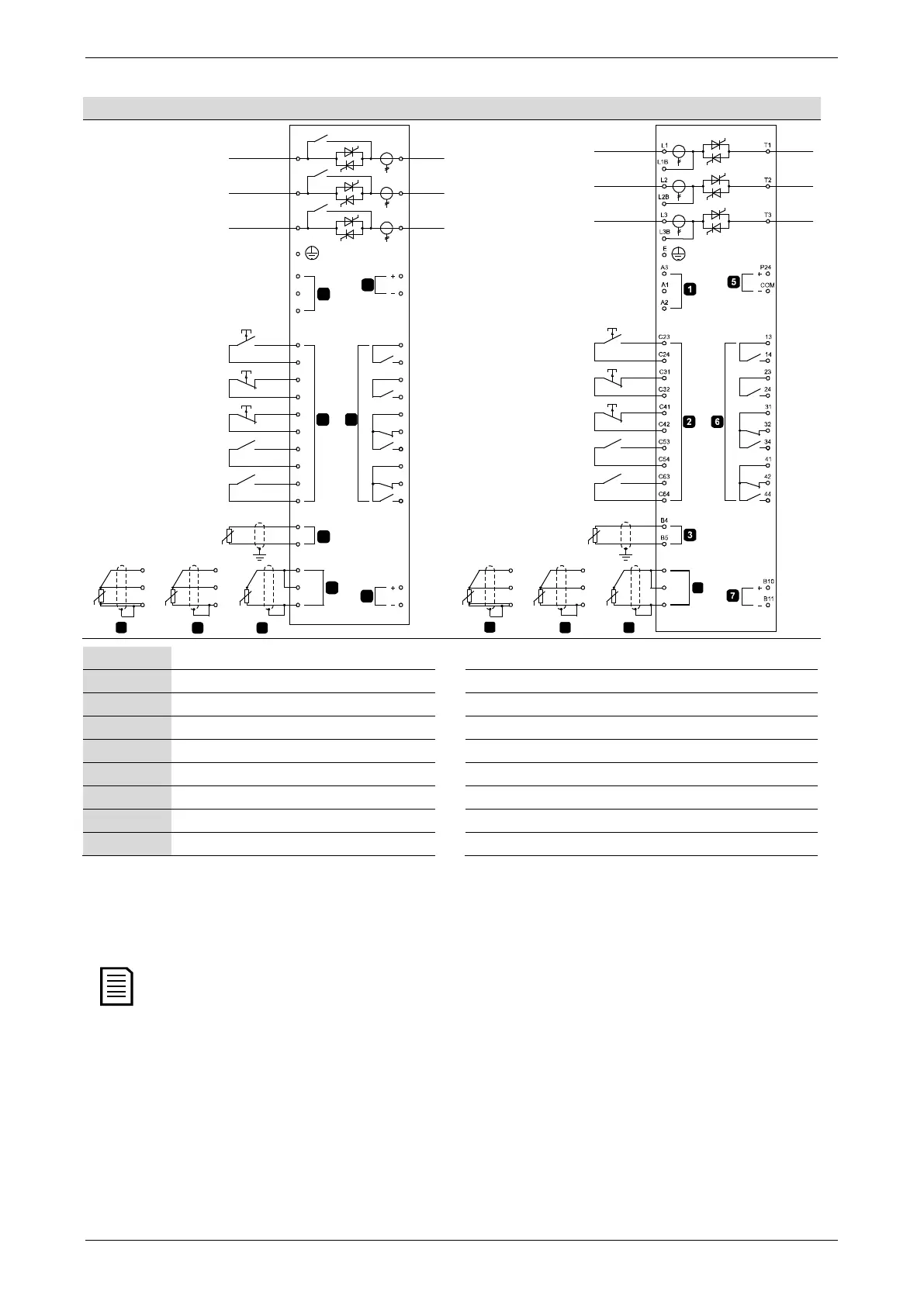
5.11 Schematic Diagrams
Internally bypassed models
04477.D
7
6
5
4
3
2
1
32
31
6/T3
2/T1
13
14
P24
COM
4/T2
24
23
34
B10
B11
41
42
44
B5
B4
C31
C32
C41
C42
C53
C54
C24
C64
C63
B7 Comp
B8 -
B6 +
A2
A1
A3
5/L3
3/L2
C23
E
1/L1
C BB A
B7 Comp
B8 -
B6 +
B7 Comp
B8 -
B6 +
4
B7 Comp
B8 -
B6 +
B7 Comp
B8 -
B6 +
B7 Comp
B8 -
B6 +
*
*
*
04480.C
C
B
B
A
Control voltage (model dependent)
C23, C24
Start
Remote control inputs
C31, C32
Stop
Motor thermistor input
C41, C42
Reset
RTD/PT100 input - 2-wire
C53, C54
Programmable input A
RTD/PT100 input - 3-wire
C63, C64
Programmable input B
RTD/PT100 input - 4-wire
13, 14
Relay output A
24 VDC output
Run relay output
Relay outputs 31, 32, 34 Relay output B
Analog output 41, 42, 44 Relay output C
Different models require control voltage to different terminals:
• C1 (110~210 VAC) A1, A2
• C1 (220~440 VAC) A2, A3
• C2 (24 VAC/VDC) A1, A3
* EMX3-0255C current transformers are located on the output. Bypass terminals are labelled T1B, T2B and T3B.
14 | User Manual (710-04840-00M)