Protected by copyright. Copying for private or commercial purposes, in part or in whole, is not
permitted unless authorised by AUDI AG. AUDI AG does not guarantee or accept any liability
with respect to the correctness of information in this document. Copyright by AUDI AG.
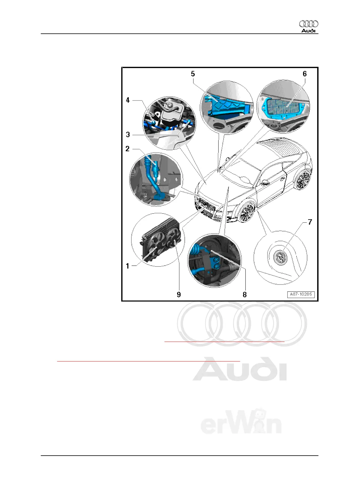
2.7 Components Outside of Passenger Compartment, Group 2
1 - Coolant Fan -V7-
❑ Different versions of the
Coolant Fan -V7- and
Coolant Fan 2 -V177-
are installed depending
on vehicle equipment.
Refer to Electronic Parts
Catalog (ETKA).
❑ The request to switch on
the Coolant Fan is sent
by the Climatronic con‐
trol module -J255- via
the databus to the en‐
gine control module.
The engine control mod‐
ule controls the (coolant
fan and coolant fan 2)
directly or by the Cool‐
ant fan control module -
J293- . Refer to ⇒
Engine Mechanical;
Rep. Gr. 19 ; Descrip‐
tion and Operation and
Vehicle diagnosis, test‐
ing and information sys‐
tem -VAS5051B- in the
"Guided Fault Finding".
❑ Check the radiator fan
control by the Clima‐
tronic control module
using the Vehicle diag‐
nosis, testing and infor‐
mation system -
VAS5051B- in the "Gui‐
ded Fault Finding".
❑ The respective engine
control modules
switches, for example,
the Coolant Fan and
Coolant Fan 2 (directly
via the Coolant Fan Control Control Module -J293- ) continuously to the desired output (depending on
engine type). Check using Vehicle diagnosis, testing and information system -VAS5051B- in the "Guided
Fault Finding" and ⇒ Wiring diagrams, Troubleshooting & Component locations.
2 - High Pressure Sensor -G65-
❑ Function, removing and installing, refer to ⇒ “5.15 High Pressure Sensor G65 “, page 151 .
❑ The High Pressure Sensor measured value is displayed in“Read measured value block“ by the Clima‐
tronic control module -J255- . Refer to
⇒ “4.8 High Pressure Sensor G65 , Checking Pressure Signal“, page 96 and Vehicle diagnosis, testing
and information system -VAS5051B- in the "Guided Fault Finding".
3 - High Pressure Side Service Connection
❑ For measuring and discharging the refrigerant circuit, refer to ⇒ Refrigerant R134a Servicing; Rep. Gr.
00 ; Description and Operation .
❑ Cap with seal, always install.
❑ Depending on engine version, it may be necessary to remove some components (for example, EVAP
canister) in order to be able to connect to service coupling.
4 - Low Pressure Side Service Connection
❑ For measuring and discharging refrigerant circuit, refer to⇒ Refrigerant R134a Servicing; Rep. Gr. 00 ;
Description and Operation .
❑ Cap with seal, always install.
Audi TT 2007 ➤
Heating, Ventilation and Air Conditioning - Edition 01.2011
2. Description and Operation 57