4. Assembly
4.1. Mounting position
The product described in this document can be operated without restriction in any
mounting position.
4.2. Mount actuator to valve
Corrosion due to damage to paint finish and condensation!
→
Touch up damage to paint finish after work on the device.
→
After mounting, connect the device immediately to electrical mains to ensure
that heater minimises condensation.
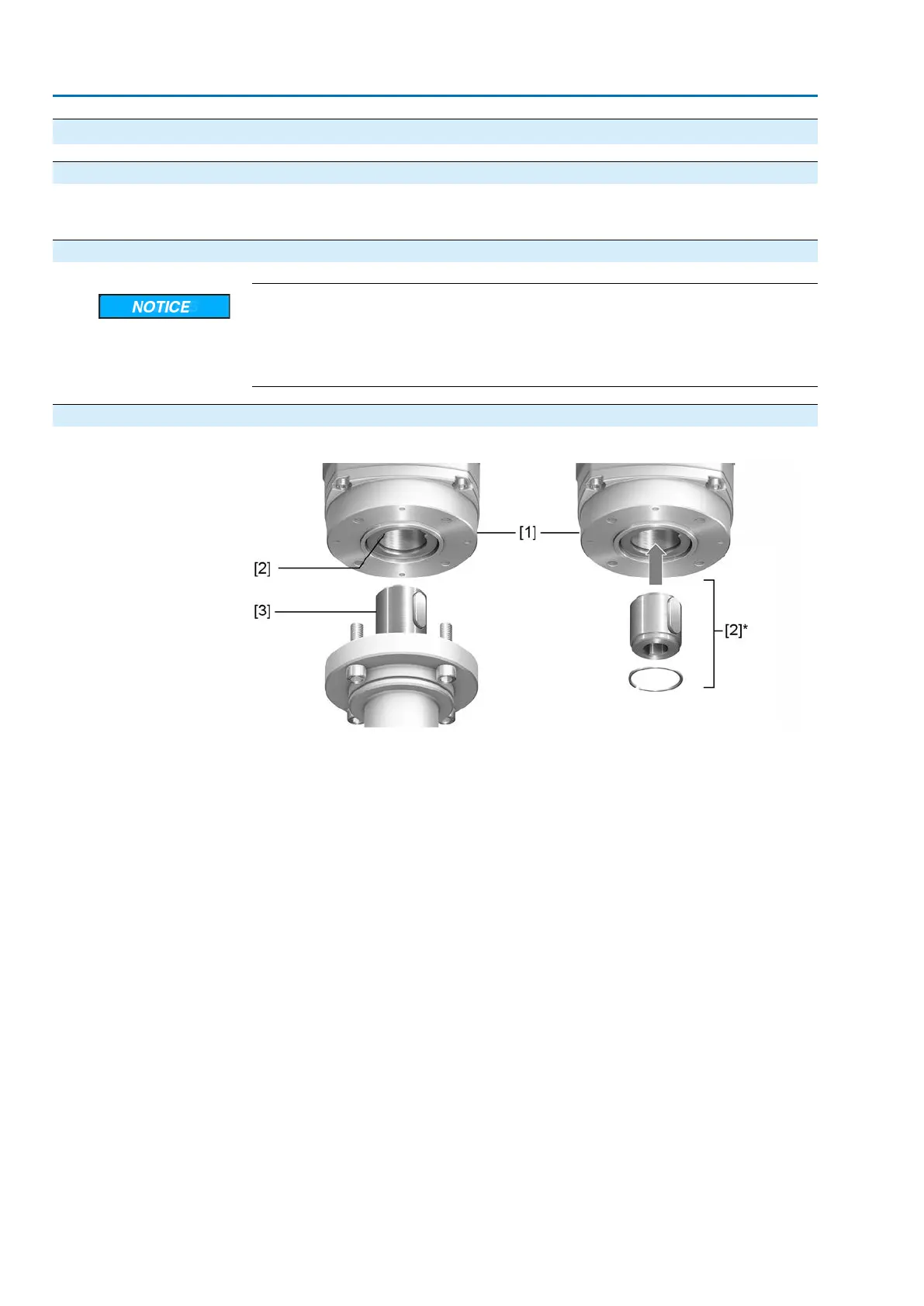
4.2.1. Design of output drive types B
Figure 8: Output drive type B
[1] Multi-turn actuator flange
[2] For output drive types B/B1/B2 solid shaft with bore and keyway
[2]* For output drive types B3/B4/E, an output drive sleeve is fitted into the bore
of the solid shaft
[3] Gearbox/valve shaft with parallel key
Information
Spigot at valve flanges should be loose fit.
For output drive types B/B1/B2, the connection to the valve or the gearbox is made
by directly placing the multi-turn actuator solid shaft (output drive shaft) onto the
input shaft of the valve or gearbox.
For output drive types B3/B4/E, the connection is made via output drive sleeve which
is inserted into the bore of the solid shaft of the multi-turn actuator and fixed by a
retaining ring.
When exchanging the output drive sleeve, later retrofitting to a different output drive
type is possible
12
SA 07.2-UW – SA 16.2-UW / SAR 07.2-UW – SAR 16.2-UW Control unit: electronic (MWG)
Assembly AC 01.2 Non-Intrusive Profinet