16
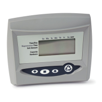
24. Cycle (C). The number displayed by #23 is the
current cycle in the regeneration sequence.
25. Hardness setting
26. Capacity display—shows estimated system
capacity.
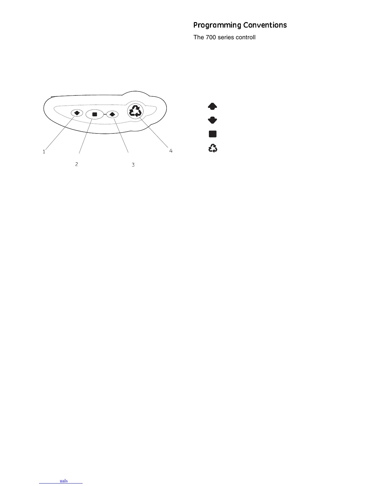
Keypad — Buttons
Figure 14
1. DOWN arrow. Generally used to scroll down or
increment through a group of choices.
2. SET. Used to accept a setting that normally
becomes stored in memory. Also used together
with the arrow buttons.
3. UP arrow. Generally used to scroll up or increment
through a group of choices.
4. Regenerate. Used to command the controller to
regenerate. Also used to change the lock mode.
Note: If a button is not pushed for thirty seconds, the
controller returns to normal operation mode. Pushing
the Regenerate button immediately returns the
controller to normal operation.
Programming Conventions
The 700 series controller is programmed using the
buttons on the keypad. The programming instructions
are described two ways whenever a section has keypad
input.
First, a table shows simplified instructions. Second, text
follows that describes the action. In each table:
"Action" lists the event or action desired.
"Keys" are listed as:
UP for up arrow
DOWN for down arrow
SET for set
REGEN for regeneration
"Duration" describes how long a button is held down:
P/R for press and release
HOLD for press and hold
X sec for a number of seconds to press the button
and hold it down
"Display" calls out the display icons that are visible.
2
1
3
4