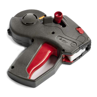
03/10 Rev. 5.04-04 SERVICE MANUAL Service Mechanics
64-xx – 64-xx Dispenser
16
Disassembling
1. Turn out the threaded rod. To do this,
turn the red hexagon head (on the side
of the print head ) in an anti-clockwise
direction. Hold the cap (1) while doing
this.
2. Detach the cap (1), spacing ring, contact
spring (2), oscillator disc (3) and brake
disc (4).
3. Unattach the brake spring (5), detach
the round belt disc (below it).
4. Unscrew the two grub screws (6) of the
start disc (7). Remove the buffer disc.
5. Remove the shims.
6. Pull the ribbon mandrel out of its bearing
to the print head side.
Pay attention to the shims on the ribbon
mandrel axle (print head side).
Assembly
1. Insert the ribbon mandrel, put on the
shim(s) and buffer disc.
2. Affix the buffer disc with both grub
screws.
3. Put on the round belt disc. Lay the brake
spring around the disc and hang it in.
4. Put on the brake disc, oscillator disc and
contact spring one after the other.
5. Push the threaded rod through.
6. Place the spacing ring on the end of the
threaded rod.
7. Screw the threaded rod into the cap until
the contact spring is compressed by a
few millimetres.
Turn the cap when putting it on until it
can be easily moved along the ribbon
mandrel axle.
Continued on the next page.
1
2
7
6
5
4
3