Chapter 8: Wiring Diagrams and Pin Assignments 71
Chapter 8: Wiring Diagrams and Pin
Assignments
LTC Connectors
SYNC HD LTC In and LTC Out connectors are
balanced XLRs with Pin 2 wired “+” or “hot,” Pin
3 wired “–” or “cold,” and Pin 1 wired to ground
(shield). Depending on whether you are connect-
ing a balanced or unbalanced signal to these con-
nectors, different wiring configurations are recom-
mended for optimum signal integrity, especially
for long cable runs.
If you are connecting a balanced signal to the
SYNC HD LTC In or LTC Out connectors:
• Pin 1 and ground should be connected at the in-
put only (not at the output). This will prevent
ground loops between the shield and the Pin 1
conductor.
If you are connecting an unbalanced signal to the
SYNC HD LTC In or LTC Out connectors:
• Connect only Pin 2 to the “+” signal;
• Connect Pin 1 to ground at all inputs and out-
puts.
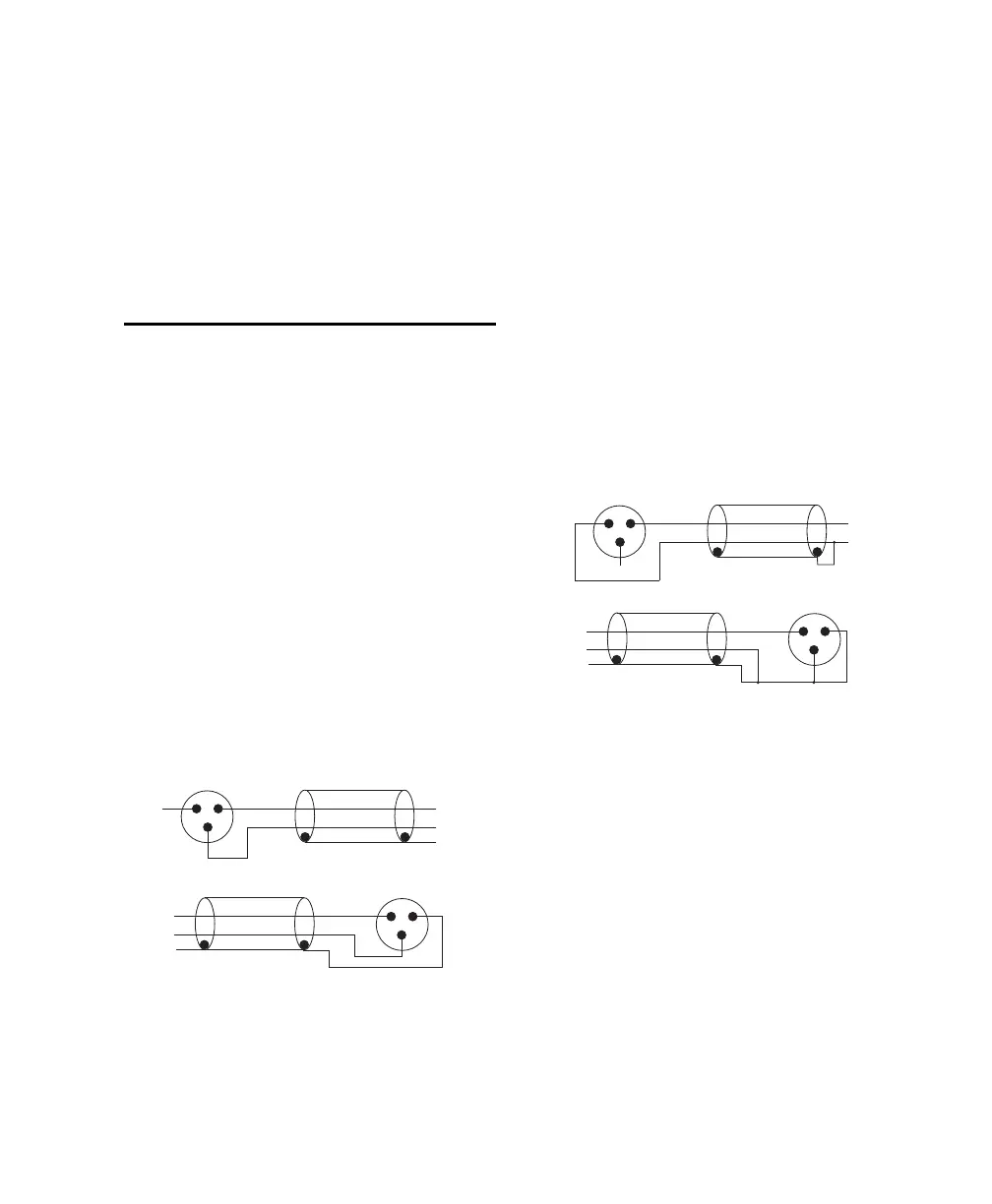
Wiring diagrams for the SYNC HD LTC In and
LTC Out connectors (balanced signal)
LTC In
Device
LTC OutDevice
Wiring diagrams for the SYNC HD LTC In and
LTC Out connectors (unbalanced signal)
LTC In
Device
Device
LTC Out