-73-
APPENDIX 2 PIN CONFIGURATION
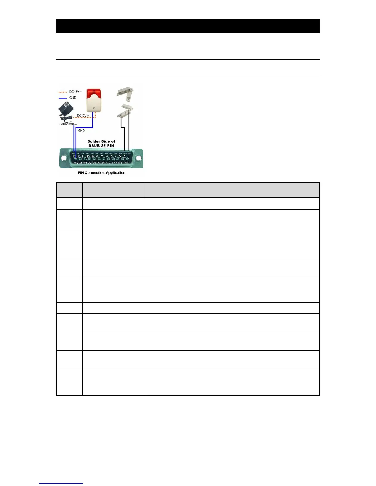
When the magnetic contact is opened, the alarm will be triggered and the recording is on. At the same time, COM
connects with NO and the siren with strobe starts wailing and flashing.
NOTE: Please go to MENU -> ADVANCE -> DETECTION -> DETECTION SETUP, and set ALARM to LOW on the
local machine.
PIN
FUNCTION
DESCRIPTION
1
GND GROUND
2~9
ALARM INPUT
When connecting the wire from ALARM INPUT (PIN 2 --
connector, DVR will start recording and the buzzer will be on.
10
PIN OFF
11
TXD232
Using RS-232 serial communication signals, DVR can be controlled remotely by
the keyboard of PC
12
RS485-A
Using RS-
485 serial communication signals, DVR can be controlled remotely by
the keyboard of PC
13
EXTERNAL ALARM NO.
Under the normal operation, COM disconnects with NO. But when any alarm is
triggered, COM connects with NO.
Attention: The voltage restriction is under DC24V 1A.
14
PIN OFF
15~22
ALARM INPUT
When connecting the wire from ALARM INPUT (PIN 15 --
connector, DVR will start recording and the buzzer will be on.
23
RXD232
Using RS-232 serial
communication signals, DVR can be controlled remotely by
the keyboard of PC
24
RS485-B
Using RS-
485 serial communication signals, DVR can be controlled remotely by
the keyboard of PC
25
EXTERNAL ALARM COM
Under the normal operation, COM disconnects with
NO. But when any alarm is
triggered, COM connects with NO.
Attention: The voltage restriction is under DC24V 1A.