Hardware Connections
9.3 Global Inputs/Outputs
9.3.1 GPIOs
The in-/outputs can be used for global functionality for example synchronization, remote function, relay
logic etc…
Each Sub-D connector represents 2 GPIO's.
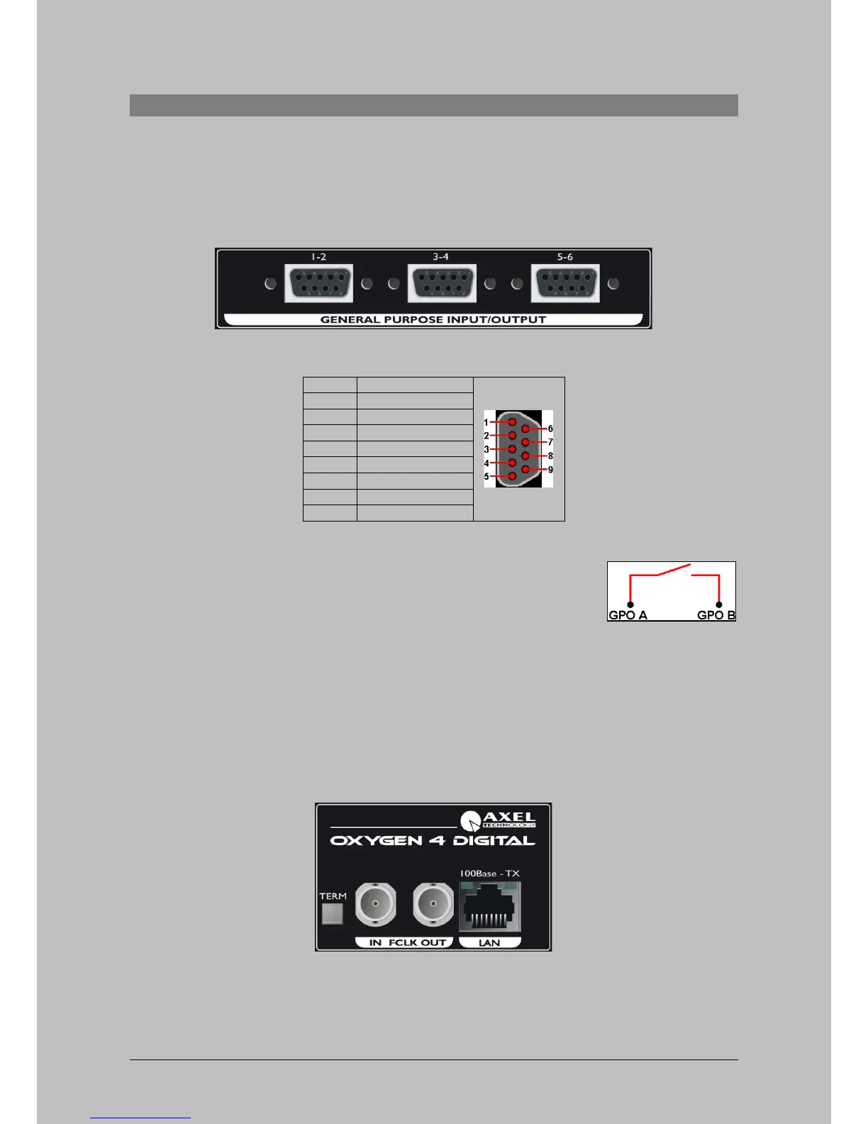
Figure 14: GPIO connections at rear side
Table 7: Pinning GPIO's
GPO-A and GPO-B make connection if the GPO is activated!
Maximum current: 200 mA
Maximum resistance when connection made: 12 Ohm
Maximum Voltage: 24 V
9.3.2 Word clock in and out.
On the rear side of the Oxygen 4 Digital you can find two BNC connectors with the text FCLK OUT
and FCLK IN. These are the word clock in/out connection which can be used for synchronization
purposes.
If the Oxygen 4 Digital is the last in the synchronization chain, you can use the TERM. switch to
terminate the line. (75 Ohm Termination)
Figure 15: Word Clock In and Out at rear side
Oxygen 4 Digital - from Axel Technology Phone +39 051736555, support@axeltechnology.com Page 24
 Loading...