Hardware Connections
9.3.6 Connection to Control Surfaces
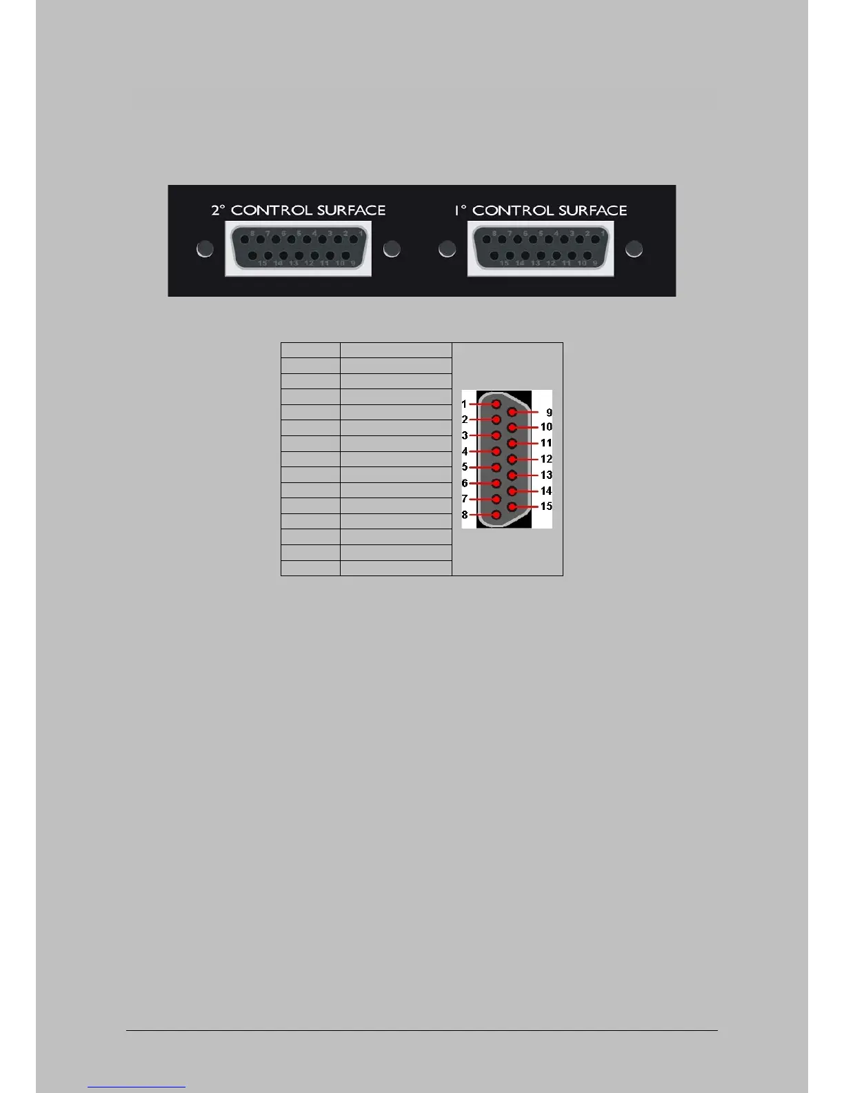
The control-unit(s) can be connected to the control-unit 1 and 2 connector. The surface connected to
connector ‘TO CNTRL UNIT 1’ will always contain module 1-4 and the surface connected to connector
‘TO CNTRL UNIT 2’ will always control module 5-8.
Figure 19: Control Surface connection at rear side
Table 8: Pinning Control Surface connector
The power-supply for the control surface comes through the 15 pin cable. It's very important to never
extend the cable any further than the maximum specified length of 5m. This is also the length of the
cable delivered with the package. If the voltage drop on the +5 volt lines becomes to large the control-
surface won't function properly.
Oxygen 4 Digital - from Axel Technology Phone +39 051736555, support@axeltechnology.com Page 26
 Loading...