BA_373-E07_04_DEF_MJ_1821
13 | 36W. Baelz & Sohn GmbH & Co. · Koepstrasse 5 · 74076 Heilbronn · Germany · www.baelz.de Seite | Page
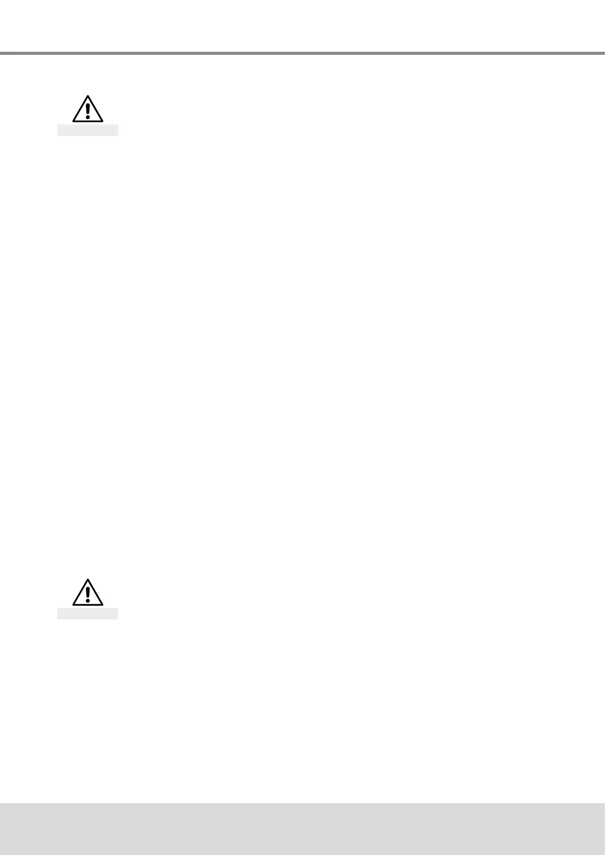
Motorized Linear Actuator baelz 373-E07
4.4 Electrical connection
Risk of electric shock!
Danger
Use an appropriate power supply to ensure that no hazardous voltage can enter the
device during normal operation or in the event of a system failure or defective system
components.
Failure to heed this warning may result in death, serious injury or substantial material
damage.
For short-circuit protection and disconnection of the actuator from the power supply, fuses and
switch disconnectors must be provided on site. The current values for the rating depend on the
operating current of the motor (refer to the nameplate).
Theelectricalconnectionshouldonlybecarriedoutbytrained,qualiedpersonnel.
● Prior to connection, observe the instructions in this chapter.
● After connection, but before applying voltage, observe the instructions in the chapter
"Commissioning"(page14).
● When making the electrical connection, be sure that the power supply is turned OFF!
Ensure protection against unintentional reconnection to the power supply!
● For wiring and connection, observe the regulations for the construction of electric power
installations and the regulations of the local energy supplier!
● Checkcomplianceofthesupplyvoltageandfrequencywiththespecicationsonthe
nameplate of the actuator and on the nameplate of the actuator motor.
● Always select the cable cross section so as to match the actuator's power consumption
andtherequiredcablelength.Minimumcrosssectionofthecableforthislinear
actuator: 1 mm²
In case of malfunction:
Dangerous voltage if protective earth conductor is NOT connected! Risk of electric shock!
→Donotoperatethedeviceiftheprotectiveearthconductorisnotconnected!
Trapped wires can lead to short circuiting! Risk of electric shock and malfunction.
4.5 Carrying out the electrical connection
Risk of electric shock!
Danger
→Disconnectthedevicefromthepowersupplybeforeremovingcover.
Always use the wiring diagram on the inside of the cover or supplied with the actuator.
Replace the dummy plugs with cable glands.
1. Strip the cable as necessary.
2. Strip the ends of the individual wires.
3. Forexiblewires:UsewireendferrulesasspeciedinDIN46228.
4. Connectthewiresasshowninthejob-specicwiringdiagram.
The IP-rating shown on the nameplate is only valid if suitable cable glands are used.