BA_373-E07_04_DEF_MJ_1821
29 | 36W. Baelz & Sohn GmbH & Co. · Koepstrasse 5 · 74076 Heilbronn · Germany · www.baelz.de Seite | Page
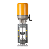
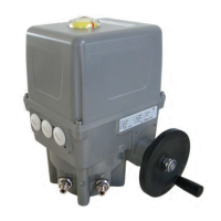
Motorized Linear Actuator baelz 373-E07
7.6 Errors
7.6.1 Errors after an initialization run
Following a successful initialization run, only the green LED is lit.
IftheredLEDisashing,thisindicatesanerrorfollowinganunsuccessfulinitializationrun.
Thersterrortooccurduringinitializationisshown.IfthegreenLEDislit,theunithadalready
beeninitializedbeforethecurrentinitializationrun.IfthegreenLEDisashing,theunithadnot
been successfully initialized previously.
The red LED shows errors occuring during initialization as follows:
Error code 1:
interval interval etc.
Error code 2:
interval interval etc.
etc. up to ...
Error code 8:
interval interval
etc..
Following an initialization run, the red LED shows only initialization errors as long as DIP switch
12issetto1.Thisenablesacleardierentiationbetweenerrorsoccuringduringinitialization
and those occuring during normal positioner operation. Setting DIP switch 12 from 1 back to 0
permits the red LED to show any normal operational errors instead of initialization errors which
may have occured.
Error code Error Corrective action
1 → 1 x
Invalid status of initialization run. Possible
cause: EMI (electromagnetic interference).
Remove source of interference.
2 → 2 x
Sensor malfunction at analogue input AI1:
No signal from potentiometer.
Check connection terminals 91, 92, 93
(see wiring diagram, Fig. 24, page 22).
Replace potentiometer if necessary.
3 → 3 x
Potentiometer value at AI1 too small.
Possible cause: EMI.
Remove source of interference.
Replace potentiometer if necessary.
4 → 4 x
Potentiometer value at AI1 too large.
Possible cause: EMI.
Remove source of interference.
Replace potentiometer if necessary.
5 → 5 x
Wrong direction of travel Check motor (97, 98, 99) and potentiometer
(91, 92, 93) connections (see wiring diagram,
Fig. 24, page 22).
Remove source of interference.
6 → 6 x
Obstruction: potentiometer or motor not moving. Checkconnections,setN↔Sswitchto"N",
remove any obstructions.
7 → 7 x
Stroke too long. Fit actuator to a valve with nominal stroke
length < 22 mm.
8 → 8 x
Stroke too short. Fit actuator to a valve with nominal stroke
length > 8,7 mm, remove any obstructions.