22 | 36W. Baelz & Sohn GmbH & Co. · Koepstrasse 5 · 74076 Heilbronn · Germany · www.baelz.de Seite | Page
I
91
6 7 8 9 12
DO4 Switch-point set = 0
-
> 1
Split-range
Split-range
Split-range
Characteristic for actuator
Operating mode 0=DIP / 1=RS485
Initialization start=0
-
>1 stop=1
-
>0
DO3 Switch-point set = 0
-
> 1
AI2 0 = U / 1 = I
DIP-Switches
1
A
B
RS 485
1 2 3 4 5 6 7 8 9 10
Tel. 07131/1500-0 Fax. 07131/150021
Koepffstraße 5. D-74076 Heilbronn
Sohn
VD: A4_EL-AS
Zeichnung:
Ursprung:
ASB_7020_V1.3.skf
Änderung
Gepr.
Bearb.
Datum
TS
04.07.17
W.Bälz
&
Anschlussbild baelz 7020
Co.
&
GmbH
Blatt
2 3 26 38
Digital Positioner baelz 7020
GND
A
R= 5kOhm
PE
N
L
+
-
Bl
M
Rd
Ye
12
Lo/DO1
14
Lu/DO2
20
DI
22
24V
23
AO1 (U)
24
GND
25
AO2 (I)
93 92
AI1
Lin
Lout
S1
54 97 98 99
Bl
Bn
Rd
AI2
U
0
I
0/2...10V
+
-
0/4...20mA
U
0
-
+
39 40
B
GND
Ty18
Rd
M
Bl
Ye
97 98 99
Ty 6 u. Ty 130
+
-
N
Lin
2
AI2 0 = 0V/0mA 1 = 2V/4mA
3
AO1/2 0 = 0V/0mA 1 = 2V/4mA
4
Actuator-spindle 0=0V=Out/1=0V=In
5 10 11
F1
1,6A T
U
+
S = Safety operation
N = Normal operation
Code S1
E4 E5 E6E1 E2 E3
DO3 DO4
DO2
DO1
ASB_7020_V1.3
FP
OT
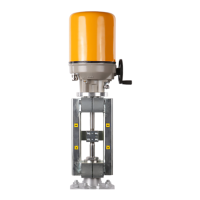
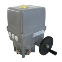
Motorized Linear Actuator baelz 373-E07
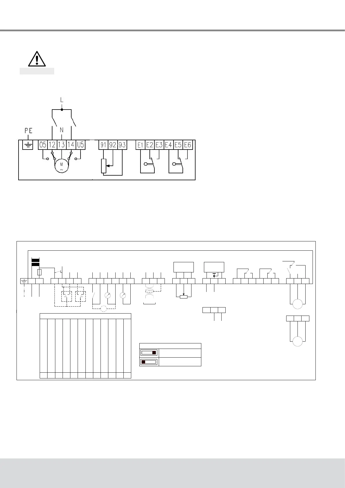
7.3 Wiring diagrams and terminal allocation
Disconnect actuator from power supply before starting work.
See also section 4.4.
Danger
7.3.1 Wiring diagrams
Fig. 23: Wiring diagram basic actuator baelz 373-
E07 with potentiometer (Fg) and 2 additional
limit switches (2EZ) as optional extras
Fig. 24: Wiring diagram digital positioner baelz 7020