20 | 36W. Baelz & Sohn GmbH & Co. · Koepstrasse 5 · 74076 Heilbronn · Germany · www.baelz.de Seite | Page
Klemme 12
Klemme 14
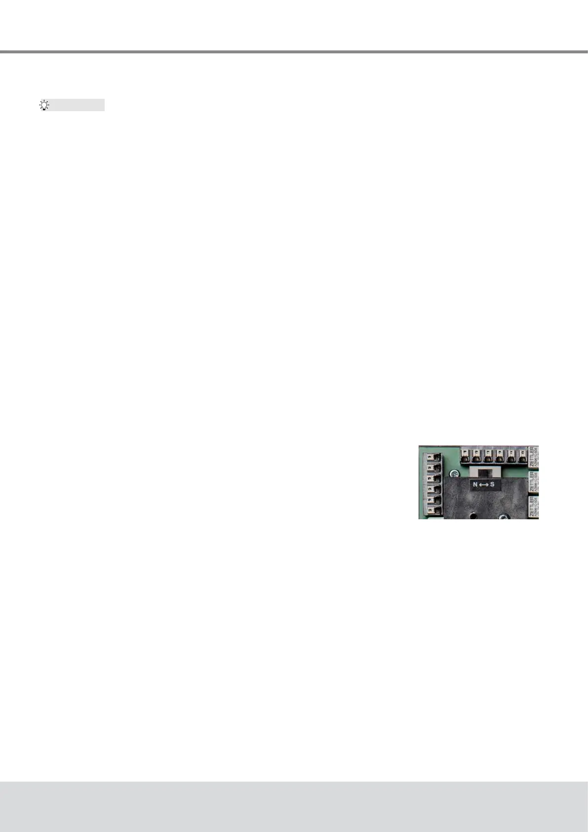
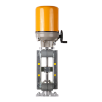
Motorized Linear Actuator baelz 373-E07
7.2 Operational modes and operating options
For further information and additional functions, see baelz 7020 operating instructions.
7.2.1 Standard operation using DIP switches
TheDIPswitchescanbeusedtocarryoutstandardcongurationsandoperations(see
section 7.4
).
When DIP switch 11 is set to 0, the 7020 is in the standard operational mode.
In standard mode, all DIP switches are active and the functions of the Baelz 7020 can be
individuallyadapted.Functionswhicharepredenedandunalterableinstandardmodeare
described in chapter 6.1 of the baelz 7020 operating instructions.
7.2.2 Standard operation using Modbus VT100 or direct addressing
In standard mode, the Baelz 7020 can be operated using Modbus VT100. For this, a virtual
7020 display and a virtual 7020 keypad are transmitted to a user interface. Modbus direct
addressing, e.g. from a building automation system, enables access to status information and
allowsoperationandconguration.(Seebaelz7020operatinginstructions,AppendixA).The
settings given by the DIP switches remain active. Values which are only relevant in Modbus
modecanbeadjustedinstandardmode,butonlytakeeectinModbusmode.
7.2.3 Modbus mode
When DIP switch 11 is set to 1, the Baelz 7020 is in Modbus mode. In Modbus mode, the
7020isatitsmostexibleandcanbeconguredandoperatedusingeitheraModbusVT100
or Modbus direct addressing, for example in a building automation system. See separate
operatinginstructions"Baelz7020DigitalPositioner-OperatingInstructionsforModbusmode"
7.2.4 Normal and safety modes
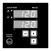
In normal mode the position of the valve is controlled by the set value at
analogueinputAI2.TheN↔Sswitchshowninthepictureontheright
is set to normal mode (N). In normal mode, no external control systems
can be connected to terminals 12 and 14.
7.2.5 Safety mode: freeze protection and excessive
temperature
In safety mode the actuator can be sent to a safe position (extended / retracted, depending on
the direction of action of the valve) in case of failure or malfunctioning of the microcontroller.
To operate the Baelz 7020 in connection with an external freeze protection and/or excessive
temperaturethermostat,settheN↔Sswitchtosafetymode(S).
Connect the freeze protection and/or excessive temperature thermostat according to desired
function and priority. Be sure to take the direction of action into account! See wiring diagrams
in the baelz 7020 operating instructions.
Tip:
Fig. 20: N↔S-switch