BA_373-E07_04_DEF_MJ_1821
17 | 36W. Baelz & Sohn GmbH & Co. · Koepstrasse 5 · 74076 Heilbronn · Germany · www.baelz.de Seite | Page
Motorized Linear Actuator baelz 373-E07
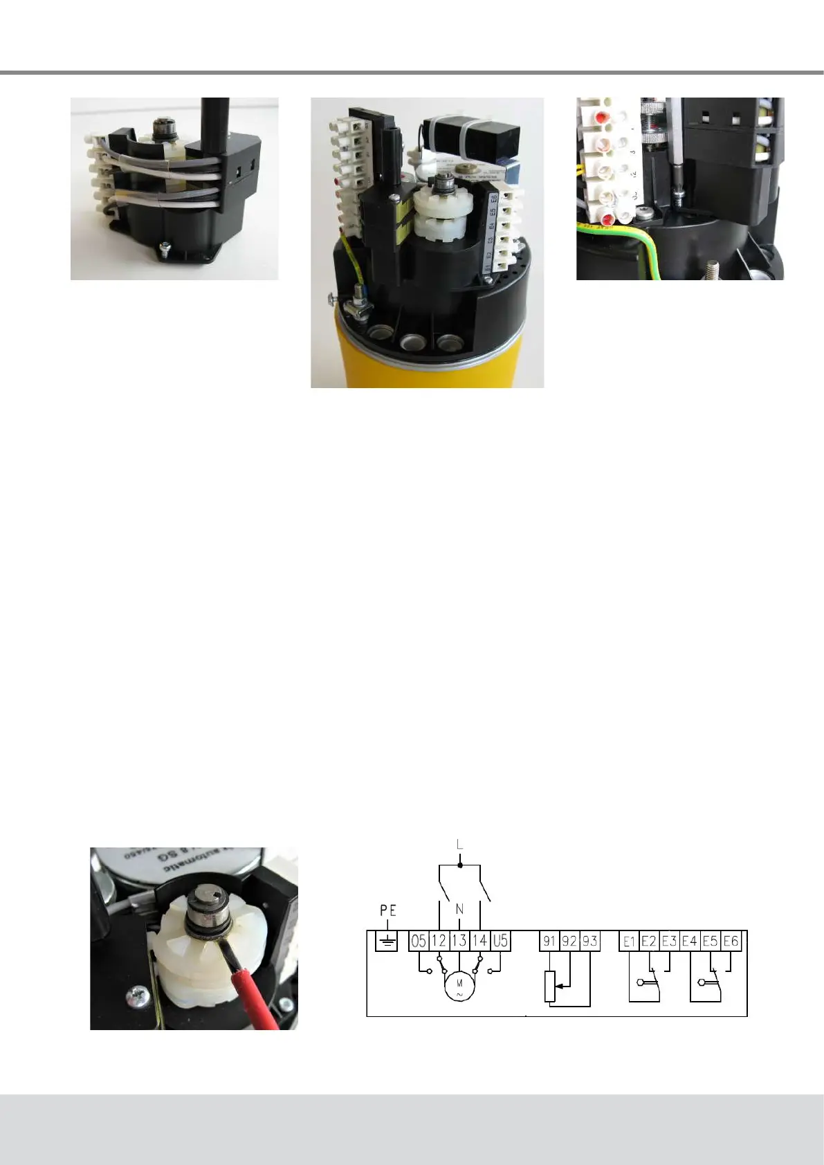
Fig. 11: Put this screw
into place before
tting
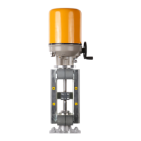
Fig. 12: 2EZ assembly on
E07 actuator
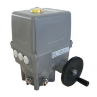
Fig. 13: Tighten the
screws
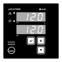
Fig. 14: Adjusting the
switching cams
6.2.1 Adjusting the switching points
The 2EZ assembly has two pairs of cams, each of which activates a switch. For each switch,
two switching points can be set using its cam pair.
Inordertosetthedesiredswitchingpoints,settheactuatortotherstpositionandadjustone
ofthetwocamssothatitactivatestheswitchinthisposition(Fig.14).Ifrequired,thisprocess
may be repeated with a second actuator position and the other cam in the pair.
Wire up the outputs E1-E3 or E4-E6 (wiring diagram Fig. 15).
Fig. 15: Wiring diagram baelz 373-E07
with 2EZ and potentiometer
● Putoneofthe3TorxT10buttonscrewsintoplace,asaccesshereisdicultwhenthe
2EZ assembly is in place, see Fig. 11.
● Fit the 2EZ assembly onto the acutator so that the raised lip around the pinion hole sits
intheholeontheactuatorandthe3xingholesinthe2EZassemblyarealignedwith
thexingholesintheactuator(Fig.12).
● Fix the 2EZ assembly with the 3 Torx T10 button screws (Fig. 13).