www.baldormotion.com
3-22 Basic Installation MN1901
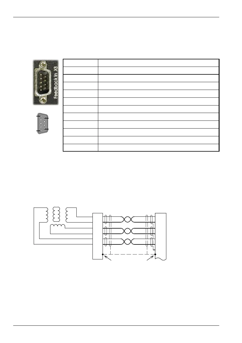
3.7.1 Resolver option - X8
The resolver connections are made using the 9-pin D-type male connector X8. T wisted pair
cables must be used for the complementary signal pairs e.g. SIN+ and SIN-. The overall cable
shield (screen) must be connected to the metallic shell of the D-type connector .
Location
Connector X8, 9-pin D- type male connector
Pin Resolver function
1 REF+
2 COS+
3 SIN+
4 (NC)
5 Analog Ground
6 REF-
7 COS -
8 SIN-
9 Chassis Ground
Description Resolver input with 14-bit resolution
The resolver input is used to create an encoder signal inside the MintDrive
II
. This provides the
MintDrive
II
with an equivalent resolution of 4096 pulses per revolution (ppr), although this can
be reconfigured in the Mint WorkBench Commissioning Wizard to provide 1024 ppr. The
MintDrive
II
provides an input accuracy of ±3 counts. When used with a typical Baldor BSM
series resolver motor the combined accuracy is ±11 counts (calculated with the input
equivalent resolution set to the factory preset value of 4096 ppr).
1
6
2
7
3
8
5
R2
R1
S2
S4
S1S3
X8
SIN+
SIN-
COS+
COS-
REF+
REF-
AGND
+
Twisted
pairs
Baldor motor
resolver connector
5
6
3
4
1
2
Connect overall shiel d
to connector backshells.
Connect internal
shields to AGND.
+
+
Figure 11 - Resolver cable connections
1
5
6
9
Artisan Technology Group - Quality Instrumentation ... Guaranteed | (888) 88-SOURCE | www.artisantg.com
 Loading...
