www.baldormotion.com
4-20 Input / Output MN1901
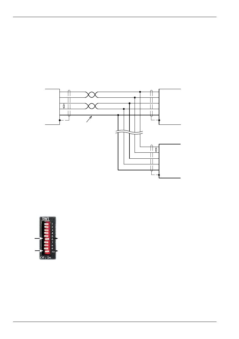
4.4.5 Multidrop using RS485 / RS422 cable
Multidrop systems allow one device to act as a ‘network master’, controlling and interacting
with the other (slave) devices on the network. The network master can be a controller such as
aMintDrive
II
, a host application such as Mint WorkBench (or other custom application), or a
programmable logic controller (PLC). RS422 may be used for multi-drop applications as
shown in Figure 44. Four-wire RS485 may be used for single point-to-point applications
involving only one Baldor controller. If firmware is updated over RS485/RS422, it can only be
downloaded to the drive that was chosen in the Select Controller dialog in Mint WorkBench.
Master and final slav e are
shown with terminating
resistors, T
R
, typical value
120Ω.
Front panel DIP switch 6 may
be used to connect an i nternal
120Ω terminating resistor
.
Network slave
T
R
RX-
DGND
RX+
TX+
TX- RX-
DGND
RX+
TX+
TX-
RX-
DGND
RX+
TX+
TX-
Twisted pairs
T
R
Connect overall shiel d
to connector backshell.
Network slave
Network
master
DGND may be one wire
from a third twisted pair.
Figure 44 - 4-wire RS422 multi-drop connections
Any MintDrive
II
on the network must have its SW1 DIP switch 10 (located
on the front panel) set to the On position (see also section 3.9.6). This will
set the serial port to RS422/RS485 mode after the next power off/on cycle.
When SW1 DIP switch 6 is set to the On position, a 120Ω termination
resistor is connected between the RX+ and RX- signals.
Each TX/RX network requires a termination resistor at the final RX
connection, but intermediate devices must not be fitted with termination
resistors. An exception is where repeaters are being used which may
correctly contain termination resistors. Termination resistors are used to match the impedance
of the load to the impedance of the transmission line (cable) being used. Unmatched
impedance causes the transmitted signal to not be fully absorbed by the load. This causes a
portion of the signal to be reflected back into the transmission line as noise. If the source
impedance, transmission line impedance, and load impedance are all equal, the reflections
(noise) are eliminated. Termination resistors increase the load current and sometimes change
the bias requirements and increase the complexity of the system.
On10
On6
Artisan Technology Group - Quality Instrumentation ... Guaranteed | (888) 88-SOURCE | www.artisantg.com
 Loading...
