www.baldormotion.com
Basic Installation 3-25MN1901
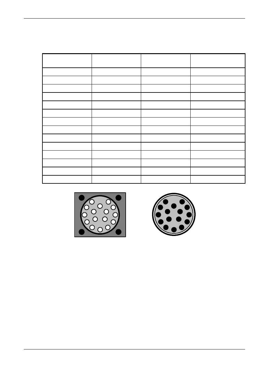
3.7.2.1 Encoder cable pin configuration - rota ry motors
Figure 14 shows the pin configuration for a typical Baldor encoder feedback cable, part
number CBL025SF-E1.
Signal name
MintDrive
II
X8 pin
Motor / cable
pin
Baldor encoder cable
internal wire colors
CHA+ 1 3 Purple
CHA- 6 4 Purple / White
CHB+ 2 5 Green
CHB- 7 6 Green / White
CHZ+ 3 7 Brown
CHZ- 8 8 Brown / White
Hall U+ 4 10 Pink
Hall U- 5 11 Pink / Black
Hall V+ 10 12 Yellow
Hall V- 15 13 Yellow / Black
Hall W+ 9 14 Grey
Hall W- 14 15 Grey / Black
+5V 11 1 Red
DGND 13 2 Blue
Motor encoder connector
(male)
Pins 9 and 16
are not
connected
1
2
3
4
5
6
7
8
9
10
11
12
13
1415
16
Cable connec tor end view
(female)
1
2
3
4
5
6
7
8
9
10
11
12
13
14 15
16
Figure 14 - Baldor rotary motor encoder cable pin configuration
The maximum recommended cable length is 30.5m (100ft).
Artisan Technology Group - Quality Instrumentation ... Guaranteed | (888) 88-SOURCE | www.artisantg.com
 Loading...
