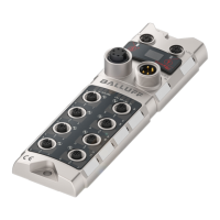
Balluff Network Interface CC-Link IE Field Basic
www.balluff.com
The LEDs on the module indicate the status of the module and its ports. The following
situations may occur:
US/UA LED is red / red flashing
There is undervoltage on the US/UA supply.
Check the voltages and their installation.
There is no CC-Link IE Field Basic
communication taking place.
Start cyclic CC-Link IE Field Basic
communication.
L/A1/2 goes off or never comes on
Check whether the Ethernet cables are
correctly installed.
Check whether 100 BASE-T Ethernet cables
are used.
Check whether the distance between
stations is 100m or less.
If you are using a switch, check whether it is
turned on.
Check whether:
- There is no actuator warning.
A configured output may not be used as
an input.
- There is no overload. An output can
handle max. 2A.
Both port LEDs are red flashing
Check whether:
- There is no short circuit or high load on
Pin1.
Display in the
process data
In the word process data range RWrm00
h
-RWrm02
h
status messages, warnings and errors are
shown. If an error is present the RWrm00
h
.b10 bit is set. If there is a warning, the RWrm00
h
.b12
bit is set.
The corresponding error codes are found in Register RWrm01
h
. The warning codes are found
in Register RWrm02
h
.

 Loading...