min. Ø D2
1)
1)
Min. ØD2=Minimum diameter of the bore (seeTab. 4-1)
Fig. 4-1: Installation in non-magnetizable material
Magnetizable material
If using magnetizable material, the transducer must be
protected against magnetic interference through suitable
measures (e.g. spacer ring made of non-magnetizable
material, a suitable distance from strong external magnetic
fields).
min. Ø D2
1)
1)
Min.ØD2=Minimum diameter of the bore (seeTab. 4-1)
Fig. 4-2: Installation in magnetizable material
Tube diameter Bore diameter D2
10.2mm At least 13mm
8mm At least 11mm
Tab. 4-1: Bore diameter if installed in a hydraulic cylinder
4.2 Preparing for installation
Installation note: We recommend using non-
magnetizable material to mount the transducer and
magnet.
Horizontal assembly: If installing horizontally with
nominal lengths > 500 mm, we recommend tightening the
outer rod at the end (only possible with Ø10.2mm) or
supporting it.
Hydraulic cylinder: If installed in a hydraulic cylinder,
ensure that the minimum value for the bore diameter of the
support piston is complied with (seeTab.4-1).
Mounting hole: The transducer comes with an M18×1.5
(ISO) or 3/4"-16UNF (SAE) mounting thread. Depending on
the version, a mounting hole must be made before
assembly.
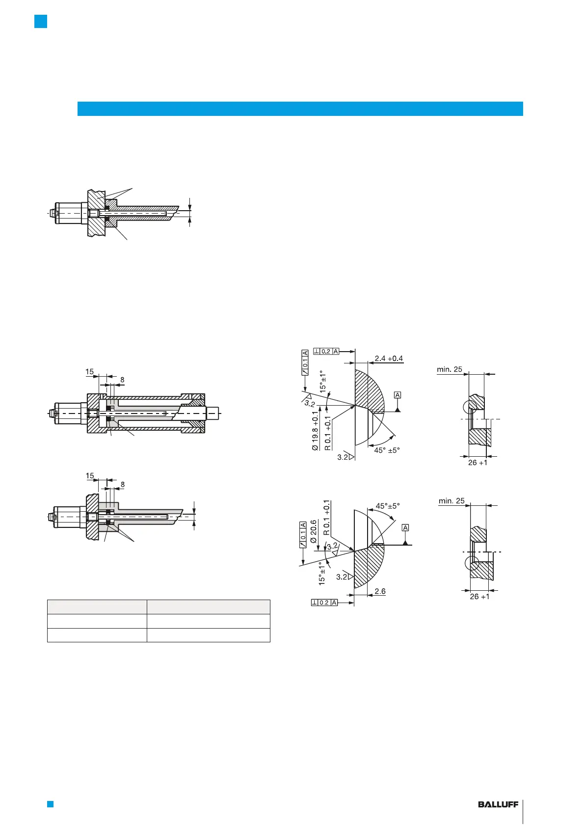
Fig. 4-3:
Mounting hole M18x1.5 per ISO6149 O-ring15.4x2.1
Fig. 4-4:
Mounting hole 3/4” 16UNF per SAE J475 O-ring 15.3x2.4
Magnet: Various magnets are available for the BTL7
transducer (see Accessories on page25).
4
Installation and connection
Non-magnetizable material
Magnet
Magnet Spacer ring made of non-magnetizable
material
Magnet
Spacer ring made of non-magnetizable
material
BTL7-A/C/E/G_ _ _-M_ _ _ _-A/B/Y/Z(8)-S32/S115/S135/S140/KA_ _/FA_ _
Micropulse Transducer - Rod Style

 Loading...


