10 english
4.3 Installing the transducer
NOTICE!
Interference in function
Improper installation can compromise the function of the
transducer and result in increased wear.
Ź The mounting surface of the transducer must make
full contact with the supporting surface.
Ź The bore must be perfectly sealed (O-ring/flat seal).
Ź Make a mounting hole with thread (possibly with
countersink for the O-ring) acc. to Fig. 4-3 or Fig. 4-4.
Ź Screw the transducer with mounting thread into the
mounting hole (max. torque100Nm).
Ź Install the magnet (accessories).
Ź For nominal lengths>500mm: Tighten the rod at the
end (only possible with Ø10.2mm) or support it.
Suitable nuts for the mounting thread are
available as accessories (see page25).
4.3.1 Installation recommendation for hydraulic
cylinders
If you seal the hole with a flat seal, the max. operating
pressure will be reduced in accordance with the larger
pressurized surface.
If installing horizontally in a hydraulic cylinder (nominal
lengths>500mm), we recommend affixing a sliding
element to protect the rod end from wear.
Dimensioning of the detailed solutions is the
responsibility of the cylinder manufacturer.
The sliding element material must be suitable for the
appropriate load case, medium used, and application
temperatures. E.g. Torlon, Teflon or bronze are all possible
materials.
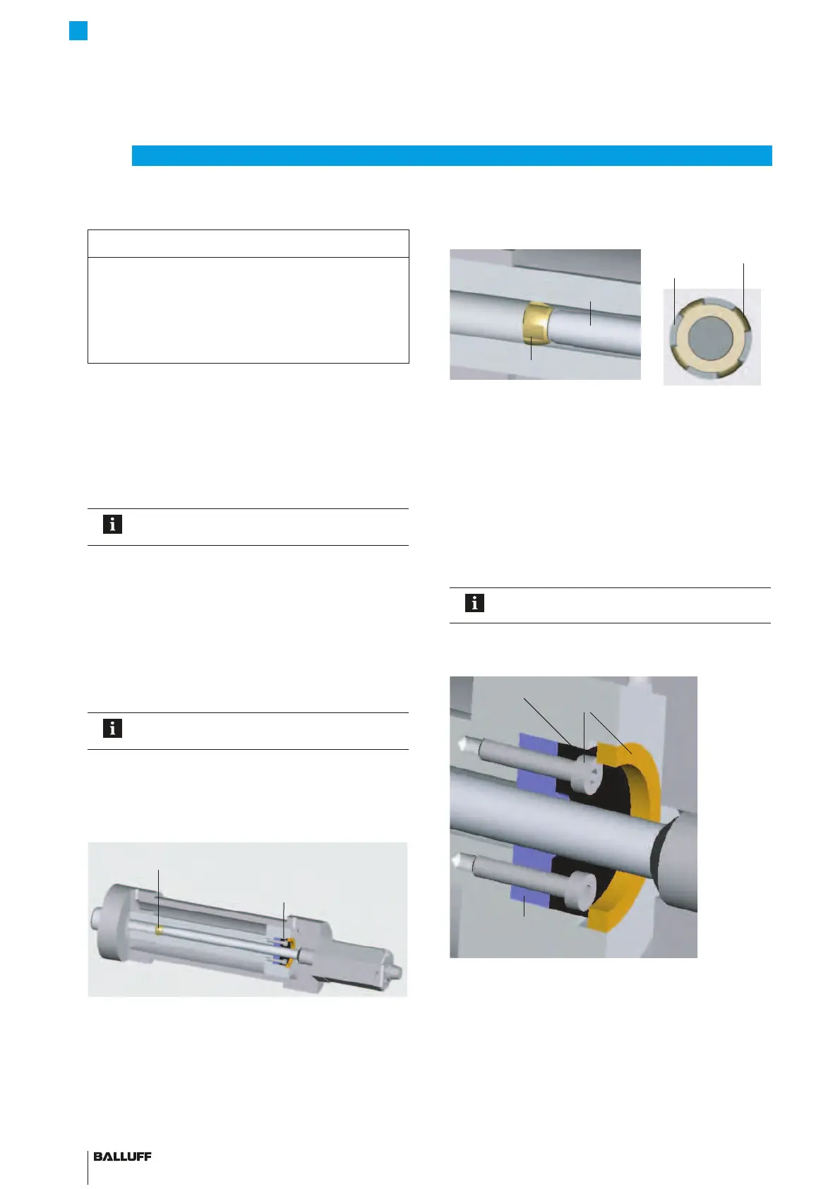
Fig. 4-5:
Example 1, transducer installed with sliding element
The sliding element can be screwed on or bonded.
Ź Secure the screws so they cannot be loosened or lost.
Ź Select a suitable adhesive.
Fig. 4-6: Detailed view and top view of sliding element
There must be a gap between the sliding element and
piston bore that is sufficiently large for the hydraulic oil to
flow through.
Options for fixing the magnet:
– Screws
– Threaded ring
– Press fitting
– Notches (center punching)
If installed in a hydraulic cylinder, the magnet
should not make contact with the rod.
The hole in the spacer ring must ensure optimum guidance
of the rod by the sliding element.
Fig. 4-7:
Fixing the magnet
An example of how to install the transducer with a
supporting rod is shown in Fig. 4-8 on page11.
4
Installation and connection (continued)
Slide element
Magnet
Piston rod
BTL rod
Slide element
Flow gap
Slide surface
Magnet
Fixing of magnet
Spacer ring
BTL7-A/C/E/G_ _ _-M_ _ _ _-A/B/Y/Z(8)-S32/S115/S135/S140/KA_ _/FA_ _
Micropulse Transducer - Rod Style

 Loading...


