20 english
8
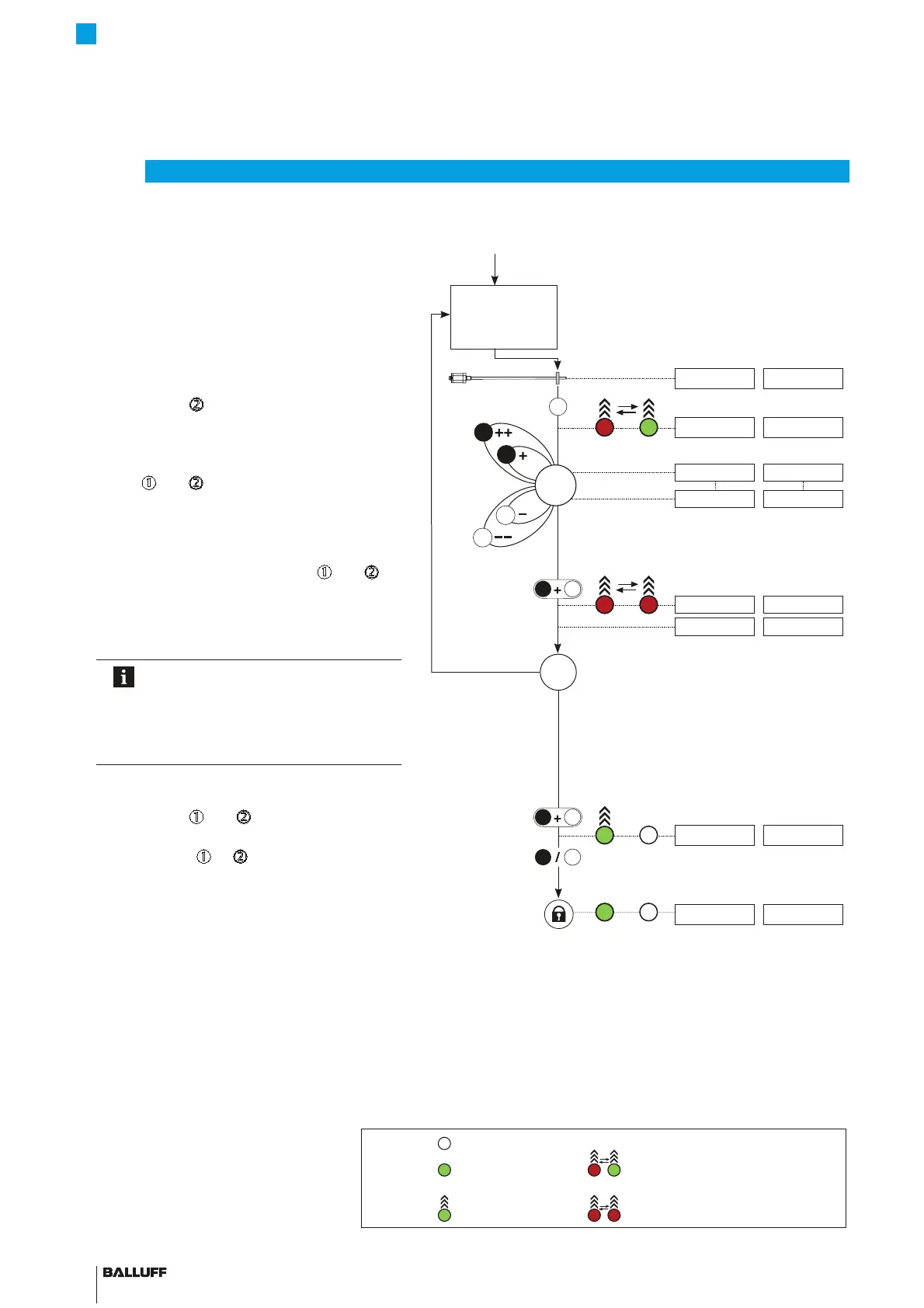
Calibration using adjustment (continued)
Adjust
start value
(see page 19)
LED display Displayed values (example)
LED1 LED2 At 0 to 10 V At 4 to 20 mA
4. Adjust end value
Ź Bring magnet to end position.
9.89 V 19.13 mA
Ź Hold down
d
for at least 2s.
> 2s
2
Indication for "Adjust end value" is displayed.
10.00 V 20.00 mA
Ź Adjust end value
The end value can be changed using
n
and
d
1)
. The gradient of the output
is changed, but the zero value remains
unchanged (see page16).
9.89 V 19.13 mA
9.00 V 19.00 mA
Ź Exit calibration procedure: Press
n
and
d
for no
more than 2s.
< 2s
1
2
Indication for "Adjustment" is displayed.
2.00V 6.00 mA
Set position value is saved.
9.00 V 19.00 mA
Check values
The settings for the start value and end
value have a mutual effect depending
on the measuring position.
Repeat steps 3 and 4 until the desired
values are exactly set.
5. Exit adjustment and deactivate buttons
Ź Hold down
n
and
d
simultaneously for at least 6s.
> 6s
1
2
Output indicates error value.
10.50 V 3.60 mA
Ź Briefly press
n
or
d
(<1s).
< 1s
2
1
Buttons are deactivated.
Current position value is displayed.
9.00 V 19.00 mA
1) Briefly press button: Current value is increased or
decreased by approx. 1 mV or 1PA.
If a button is held down longer than 1s, the step
interval is increased.
LED legend:
LED not on
LED green LED 1 and LED 2 flashing red-green in alternation
LED flashing green LED 1 and LED 2 flashing red-red in alternation
1
2
1
2
BTL7-A/C/E/G_ _ _-M_ _ _ _-A/B/Y/Z(8)-S32/S115/S135/S140/KA_ _/FA_ _
Micropulse Transducer - Rod Style
 Loading...


