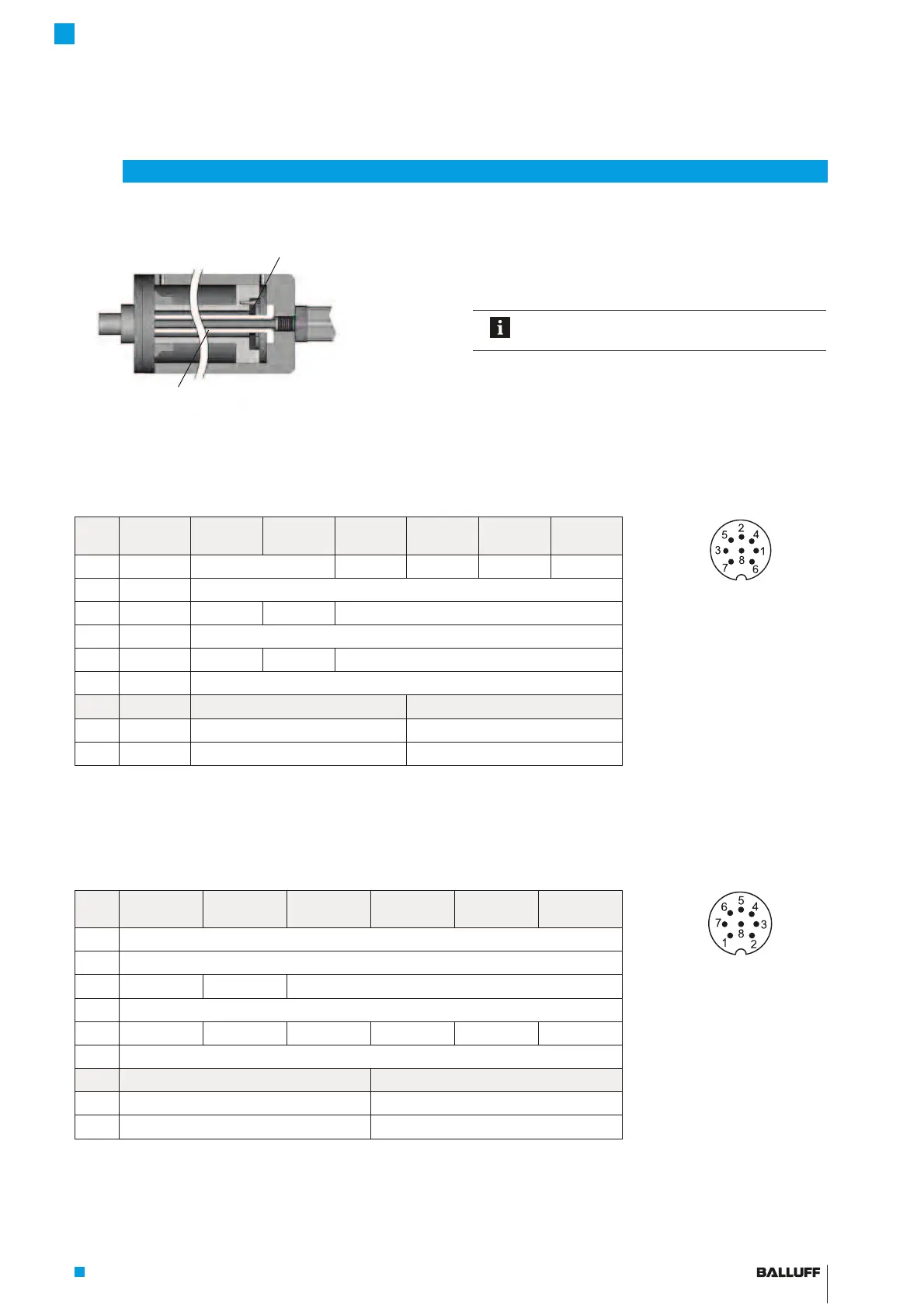
Example2, transducer installed with supporting rod
4.4 Electrical connection
Depending on the model, the electrical connection is made
using a cable or a connector.
The connection or pin assignments for the respective
version can be found in Tab. 4-2 to Tab. 4-5.
Note the information on shielding and cable
routing on page13.
4
Installation and connection (continued)
4.4.1 Connector type S32/cable connection
S32
Pin
Cable
color
-A_10 -G_10 -C_00 -C_70 -E_00 -E_70
Fig. 4-9: Pin assignment of
S32 (view of
connector pins of
transducer), 8-pin
M16 circular plug
1 YE yellow Not used
1)
0 to 20 mA 20 to 0 mA 4 to 20 mA 20 to 4 mA
2 GY gray 0 V
3 PK pink 10 to 0V 10 to 10V Not used
1)
4 RD red La (programming input)
5 GN green 0 to 10V 10 to 10V Not used
1)
8 WH white Lb (programming input)
BTL7-_1_ _-... BTL7-_5_ _-...
6 BU blue GND
2)
GND
2)
7 BN brown 20 to 28V 10 to 30V
1)
Unassigned leads can be connected to the GND on the controller side but not to the shield.
2)
Reference potential for supply voltage and EMC-GND.
Tab. 4-2: Connection assignment BTL7...-S32
4.4.2 Connector type S115
S115
Pin
-A_10 -G_10 -C_00 -C_70 -E_00 -E_70
Fig. 4-10: Pin assignment of
S115 (view of connec-
tor pins of transdu-
cer), 8-pin M12
circular plug
1 0 V (pin 3)
2 0 V (pin 5)
3 10 to 0V 10 to 10V Not used
1)
4 La (programming input)
5 0 to 10V 10 to 10V 0 to 20 mA 20 to 0 mA 4 to 20 mA 20 to 4 mA
8 Lb (programming input)
BTL7-_1_ _-... BTL7-_5_ _-...
6 GND
2)
GND
2)
7 20 to 28V 10 to 30V
1)
Unassigned leads can be connected to the GND on the controller side but not to the shield.
2)
Reference potential for supply voltage and EMC-GND.
Tab. 4-3: Connection assignment BTL7...-S115
Magnet
(e.g. BTL-P-1028-15R)
Supporting rod made of non-magnetizable material
BTL7-A/C/E/G_ _ _-M_ _ _ _-A/B/Y/Z(8)-S32/S115/S135/S140/KA_ _/FA_ _
Micropulse Transducer - Rod Style

 Loading...


