8 english
3
Construction and function (continued)
3.2 Function
The Micropulse Transducer contains the waveguide which
is protected by an outer stainless steel tube (rod). A
magnet is moved along the waveguide. This magnet is
connected to the system part whose position is to be
determined.
The magnet defines the position to be measured on the
waveguide.
An internally generated INIT pulse interacts with the
magnetic field of the magnet to generate a torsional wave
in the waveguide which propagates at ultrasonic speed.
The component of the torsional wave which arrives at the
end of the waveguide is absorbed in the damping zone to
prevent reflection. The component of the torsional wave
which arrives at the beginning of the waveguide is
converted by a coil into an electrical signal. The travel time
of the wave is used to calculate the position. Depending
on the version, this information is made available as a
voltage or current output with a rising or falling gradient.
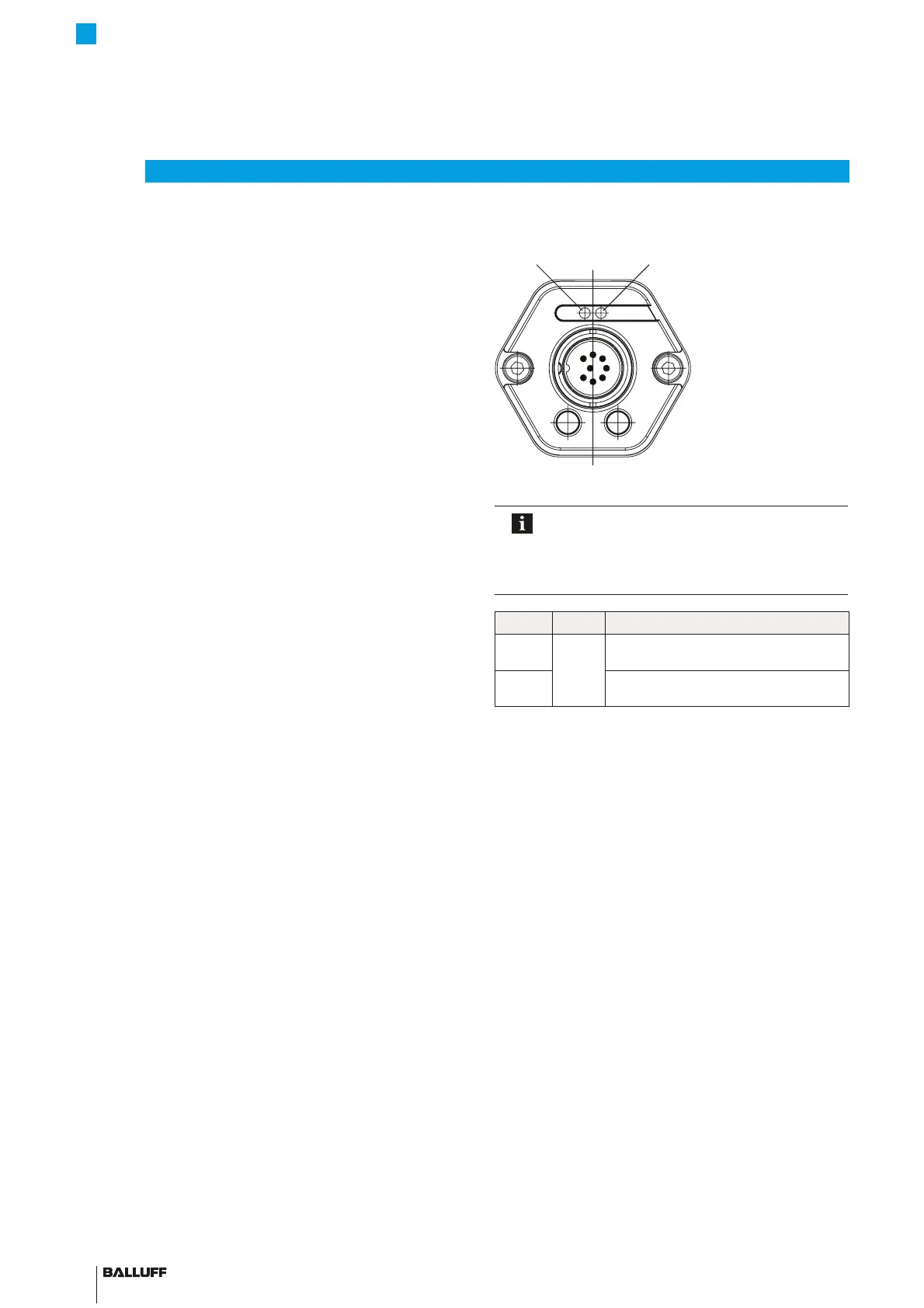
3.3 LED display
Fig. 3-2: Position of the
BTL7 LED displays
In normal operation LED 1 indicates the
operating states of the transducer. Both LEDs
together are used for displaying additional
information in programming mode
(seepage18ff).
LED1 LED2 Operating state
Green Off Normal function
Magnet is within the limits.
Red Error
No magnet or magnet outside the limits.
Tab. 3-1: LED displays in normal operation
BTL7-A/C/E/G_ _ _-M_ _ _ _-A/B/Y/Z(8)-S32/S115/S135/S140/KA_ _/FA_ _
Micropulse Transducer - Rod Style
 Loading...


