www.balluff.com 21english
9
Calibration using online setting
NOTICE!
Interference in function
Changing the transducer output signal may result in
personal injury and equipment damage if the system is
ready for operation.
Ź Persons must keep away from the system's
hazardous zones.
In online setting the system is not shut down. The start and
end values are set online.
Maximum setting range for each calibration
procedure:
Start value: ±25% of present stroke
End value: ±25% of present output value
If the desired value cannot be attained in the first
calibration procedure (max. setting range exceeded), the
calibration procedure must be started again.
1
2
1
2
1
2
1
2
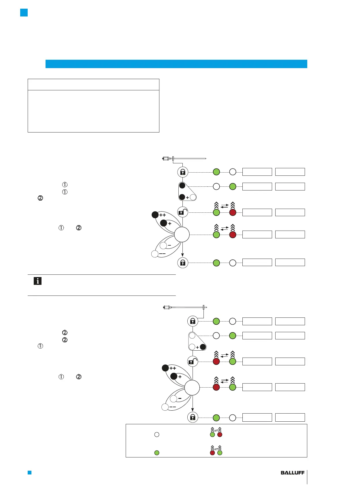
1. Set start value online: LED display Displayed values (example)
Ź Move the system so that the magnet is in the start
position.
LED1 LED2 At 0 to 10 V At 4 to 20 mA
5.39 V 12.62 mA
Ź Hold down
n
for at least 3s.
Ź Hold down
n
and additionally press
d
for at least 3s.
> 3 s
+
> 3 s
2
1
1
5.39 V 12.62 mA
Buttons are activated.
5.39 V 12.62 mA
Ź Set start value.
Using
n
and
d
, you can change the start value
within the permissible setting range
1)
. The gradient
of the output remains constant (see page16).
4.84 V 11.74 mA
Ź Exit setting (do not press a button for at least 15s).
The start value is saved, the buttons are
deactivated.
4.84 V 11.74 mA
After each calibration procedure you must wait for the
lockout time of 15s. This also applies to switching
between the start value and end value setting.
2. Set end value online: LED display Displayed values (example)
Ź Move the system so that the magnet is in the end
position.
LED1 LED2 At 0 to 10 V At 4 to 20 mA
8.72 V 17.95 mA
Ź Hold down
d
for at least 3s.
Ź Hold down
d
and additionally press
n
for at least 3s.
> 3 s
+
> 3 s
2
2
1
8.72 V 17.95 mA
Buttons are activated.
8.72 V 17.95 mA
Ź Set end value.
Using
n
and
d
, you can change the end value
within the permissible setting range
1)
. The gradient
of the output is changed, but the zero value
remains unchanged (see page16).
9.49 V 19.18 mA
Ź Exit setting (do not press a button for at least 15s).
The end value is saved, the buttons are
deactivated.
9.49 V 19.18 mA
1) Briefly press button: Current value is increased or
decreased by approx. 1 mV or 1PA.
If a button is held down longer than 1s, the step
interval is increased.
LED legend:
LED not on LED 1 and LED 2 flashing green-red in alternation
LED green LED 1 and LED 2 flashing red-green in alternation
BTL7-A/C/E/G_ _ _-M_ _ _ _-A/B/Y/Z(8)-S32/S115/S135/S140/KA_ _/FA_ _
Micropulse Transducer - Rod Style
 Loading...


