22 english
6
Start-up and operation on a Rockwell RSLogix controller (continued)
6.4 Access to input data
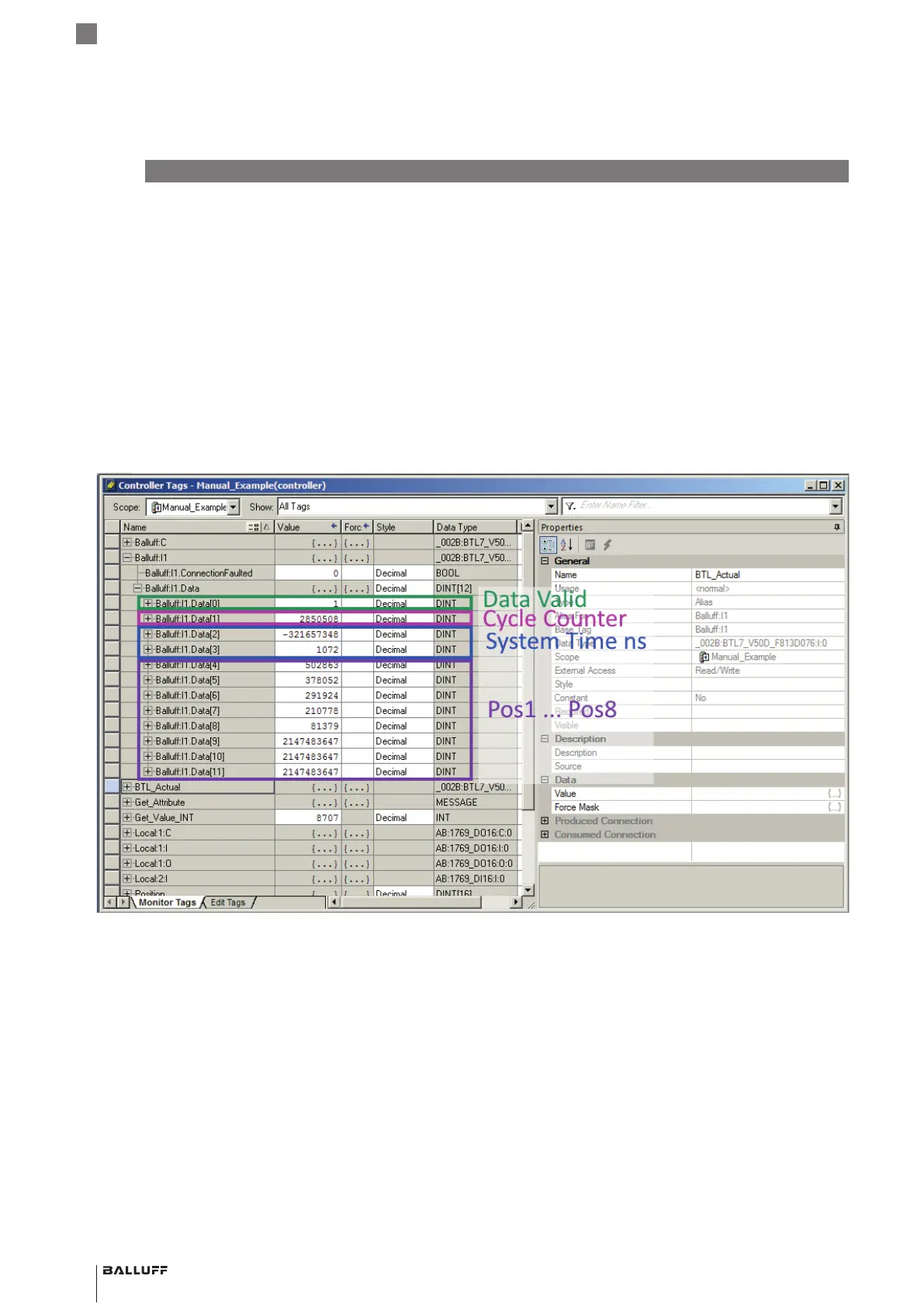
The I/O Assembly 8 x Position and Time is selected in the
example.
The first four DINT values contain the validity flag (Data
Valid), the cycle counter (Cycle Counter) and the system
time in ns (System Time ns, divided between two DINT).
Eight position values follow. Because only five magnets are
parameterized, the last three magnets (Balluff:I1.Data[9] …
[11]) are set to the error value (2147483647 =
0x7FFFFFFF). Magnet1 (Balluff:I1.Data[4]) has the highest
and magnet5 (Balluff:I1.Data[8]) the lowest position value
due to the inverted measurement direction.
Furthermore, an array BTL_Actual is set up as an alias for
Balluff:I1, which allows access to the data via an array.
BTL7-V50D-…
Configuration Manual
 Loading...


