Bandit
103Copyright 12/17
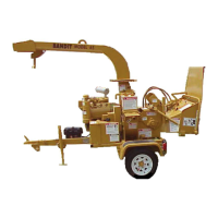
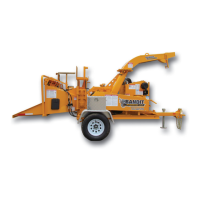
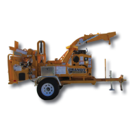
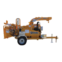
MODEL 20XP
LOCATION PART NUMBER DESCRIPTION
HYDRAULIC COMPONENTS
** Hydraulic components, ttings, hoses will very depending on optional equipment.
Order by physical description.
** Hydraulic pumps, track motors, and valve banks need to be ordered by serial number of machine.
Make sure to order components according to tting type, ttings may vary on all components.NOTICE
TRACK MACHINE
1. a. 900-3932-95 In-Tank Filter Assembly
b. 900-3931-34 Filter Element Only
2. See Page 114 - 115 Hydraulic Tank
3. a. 900-3925-22 Suction Screen - 2”
b 900-3932-06 Ball Valve - 2”
4. ** Hydraulic Pump
5. a. 900-3934-84 High Pressure Filter Assembly
b. 900-3931-35 High Pressure Filter Element Only
6. 900-3915-67 Oil Cooler
7. 900-3979-65 9 Section Valve Bank
8. ** Right Track Motor
9. ** Left Track Motor
10. 900-3906-29 Top Feedwheel Hydraulic Motor
11. 900-3906-29 Bottom Feedwheel Hydraulic Motor
12. 900-3906-29 Conveyor Hydraulic Motor
13. a. 900-3925-07 Yoke Lift Cylinder - Welded
b. 904-0007-14 Pin For Welded Cylinder (Not Shown)
c. 904-0006-90 Seal Kit - Welded Lift Cylinder (Not Shown)
14. 900-3934-24 Folding Discharge Cylinder
15. 900-3949-09 Check Valve
16. 975-300464 Return Manifold