Bandit
67Copyright 12/17
MODEL 20XP
STEPS TO INSTALL BOTH CHIPPER BEARINGS
Proper installation is critical to bearing life. Improper installation could cause premature or immediate
failure. Particular care must be taken not to create a preload on the bearings while tightening the locknut.
Use of a good quality torque wrench is also important to your safety as well as proper bearing installation.
NOTICE
SERVICING / CHANGING CHIPPER BEARING
(FOR REXNORD® 6000 SERIES)
DANGER
!
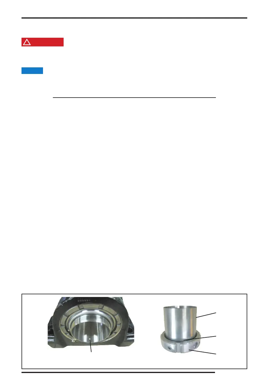
Inner Bore
Keyway
Locking
Pin
Locknut
Adapter
Sleeve
Figure 3
Before attempting any type of maintenance, disengage clutch, wait for the disc/drum to come to a complete
stop, turn o engine, remove the ignition key, make sure the ignition key is in your possession, install the
disc/drum lock pin, and disconnect the battery.
1. Clean the shaft so that it is free from burrs and rust. Do not coat the chipper shaft or the bore of the bearing
adapter with a preservative, lubricant, or other substance such as Loctite
®
.
2. If the adapter sleeve happens to get removed from the bearing during installation, the locking pin in the
adapter sleeve must be aligned with the keyway in the inner bore. See Figure 3.
3. Position the bearings on the shaft to their intended position. If the bearings do not slide freely on the shaft,
loosen the locknut until the bearing does.
Keep the weight of the drum head o the bearings while bolting the bearings down.
5. Center the chipper drum inside the base and bolt the bearing down on the right side of the machine and
tighten the four bearing bolts to 220 ft.-lbs. (298 Nm) of torque.
6. O set the chipper drum approximately 1/8” (3.2 mm) from center of the base to the left side of the machine.
7. Hand tighten the locknut to take out the looseness, then use a hook type spanner wrench to bring the
locknut to a snug t.
8. Mark the locknut and chipper drum shaft with a grease pencil or a dark marker. Use a soft steel drift pin
and a hammer to drive the locknut clockwise one full turn. Make sure the adapter sleeve does not turn on
the shaft while tightening. If the adapter sleeve is turning, it can be held by placing a hook type spanner
wrench in the split area of the sleeve.
9. Look at the visual indicators on the locknut. At least one of the visual indicators should show an indication
of de ection. See Figure 1. If at least one indicator does not show indication of tightness after 1/4 turn
beyond the nal adjustment, the locknut needs to be completely loosened and start over with step 6.
10. If the entire indicator window becomes completely blue with the possibility of yellow and red fringing, the
bearing has been over-tightened. See Figure 2. The locknut needs to be completely loosened and start
over with step 6.
11. O set the bearing on the left side of the machine about 1/8” (3.2 mm) from its intended position towards the
base, so when the bearing is tightened up on the shaft, the bolt holes will line up.
Repeat steps 7 through 10 to tighten the right side bearing on the shaft.
13. Loosen all the bearing bolts to release the preload on the bearings if there is any. Bolt both bearings down
and torque the bolts to 220 ft.-lbs. (298 Nm).
14. If the drum head does not spin freely, there is a preload on the bearings. The bearings will need to be
completely loosened and steps 3 through 13 need to be repeated.
15. Tighten the set screws in the locknut of both bearings to 13-15 ft.-lbs. (18-20 Nm) of torque with a 5/32”
hex type torque wrench.